1 FRONT PANEL CONTROLLER
1.1 Introduction
The front panel display operates in three distinct modes. The first mode is called the Run
Mode. This is the normal operation mode, where the amplifier is controlled either by the
front panel or via the GPIB/IEEE-488, the RS-232 or RS-442 interfaces. The second
mode is User Configuration. In this mode, the end user can configure the system to more
closely support their needs. The final mode is the System Calibration mode. This mode
that is designed to be used only by an authorized technician. Within the System
Calibration mode, all aspects of the amplifier configuration and calibration can be
adjusted.
1.2 Controls and Display
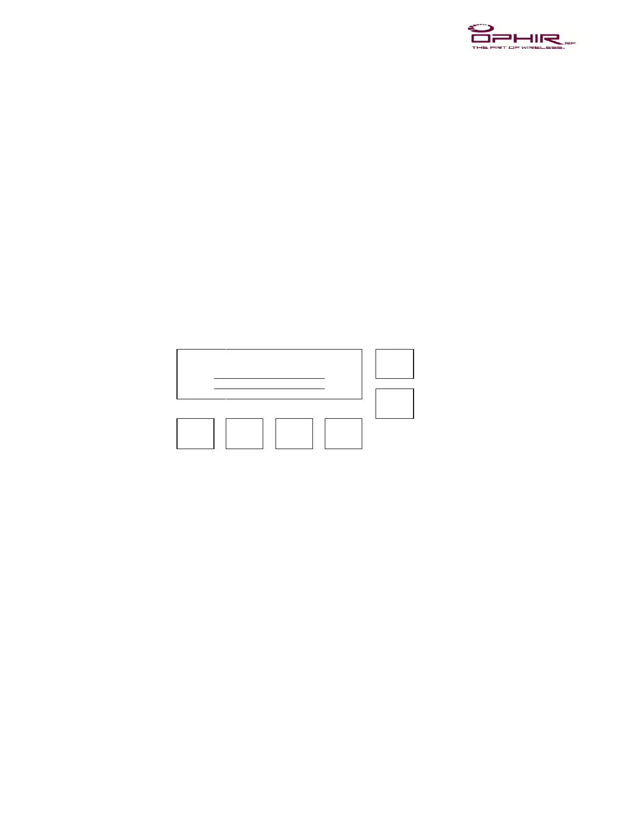
The layout of the controls and display on the front panel is depicted in Figure 1. A
description of each of the controls and the display is contained in Table 1. General
comments on the operation of the controller are contained in Table 2.
1.3 Run Mode
When the unit first powers up, a self-test operation is conducted. If any portion of the
system is un-calibrated, or an error reading the calibration data or settings is encountered,
an appropriate message will appear on the display, and the unit will not power up. If the
unit passes self-test, it will place itself in the power up mode specified by the user in the
User Configuration, or if no mode has been specified, in STANDBY with 0% Gain
(Voltage Variable Amplifier, or VVA) amplification.
1.4 User Interface
There are six buttons used to control the amplifier. The first two buttons are the UP and
DOWN buttons, which are used to set values used by the amplifier. The values that can
be changed include the amplifier output level (either specified in Gain % or dBm), and
the VSWR alarm point. The next button is the GAIN button. If pressed, this button places
the unit into the VVA mode. It also changes the display so that the VVA level can be
changed – “Set VVA: xxx.x%”. The next button is the ALC button. If pressed, this button
places the unit into the ALC mode – “Set ALC: xx.x dBm”. It also changes the display so