Appendix A
This Document contains proprietary and confidential information of Ophir RF Inc.
March 28, 2023 Rev: H
that the ALC level can be changed. The next button is the STANDBY button. This button
does double-duty. If there is a fault that has not been acknowledged, the fault is
acknowledged when this button is pushed. For more information on faults and clearing
them, please see the fault section of this document. The STANDBY button also places
the unit into and removes it from standby mode. The final button is the MODE button.
When pressed, this button cycles through the system status displays. For more
information on these displays, please see the display section of this document.
1.5 Display
The display is used in conjunction with the mode button to display the current amplifier
status. Pressing the MODE button cycles through all of the status displays. See the tables
later in this document for summaries of the displays in the different operational modes.
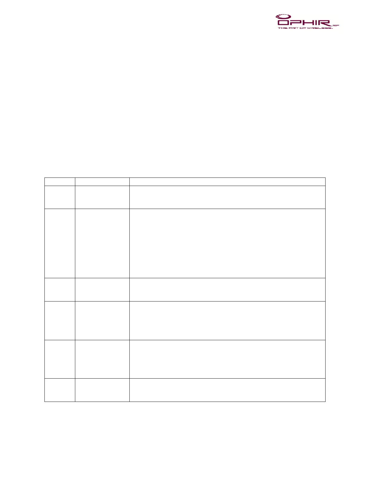
Table 1. Run-Mode Controls and Display Descriptions
Displays information on command from the microprocessor based on
queries from the front panel control switches, IEEE interface, or from
fault detection circuitry.
Allows toggling thorough all of the following:
o Gain Control (Adj. Output power)
o Forward and Reflected power
o Max Power (FWD, REV)
o VSWR Cut off (Fwd - Rev in dB)
o Gain (VVA) Voltage in %
o Monitors (8 inputs, If Applicable),
o IEEE-488 (GPIB) interface address
o Firmware revision
Places the amplifier in minimum gain mode (Gain/VVA @ 0%
voltage). The standby condition is indicated via the LED on Standby
button.
Turns ALC (Automatic Level Control) mode ON and VVA (Variable
Voltage Attenuator) control mode (also known as the GAIN mode)
OFF. The ALC mode is on when the LED on ALC button is
illuminated. This button is used in conjunction with the UP/DOWN
buttons to change the ALC setting in 0.1 dB steps.
Turns VVA control mode ON and ALC mode OFF. ON is indicated
when the LED on GAIN button is illuminated. This button is used in
conjunction with the UP/DOWN buttons to change the Gain of the
amplifier through 0.1% steps. Note that the percentage of gain is a
relative function and is not linear.
Controls gain of the amplifier when in the Gain mode and the output
level when in the ALC mode. These buttons manipulate various
parameters depending on the operating mode of the amplifier.