(1) Connector
(2) Sensitivity Potentiometer
(3) Mode Setting Switches
( Area Depth Adjustment, Auto Learning Timer,
Frequency, Rain Mode, Snow Mode )
(4) Area Width Switch
(5) Threshold Area Angle Screw
(6) Threshold Area Angle Gauge
(7) Swing Area Angle Gauge
(8) Swing Area Angle Screw
(9) Mounting Holes
(10) Operation Indicator
OPERATION INDICATOR
THRESHOLD AREA
SENSITIVITY
POTENTIOMETER
MaxMin
SWING AREA
SENSITIVITY
POTENTIOMETER
0deg
+5deg
‑5deg
DEEP
SHALLOW
SWING AREA DEPTH ADJUSTMENT
0deg
+5deg
‑5deg
DEEP
SHALLOW
FREQUENCY SWITCH
1
3
2
3
Each number of Area
can be eliminated
by using each dip‑SW.
AREA WIDTH SWITCH
OA-603
DEEP
SHALLOW
DEEP
SHALLOW
DEEP
PATTERN
SHALLOW
PATTERN
THRESHOLD AREA DEPTH ADJUSTMENT
AUTO LEARNING TIMER
1 2
15SEC.
1 2
1 2
1 2
6
DEEP
6
SHALLOW
AREA DEPTH
MaxMin
5
NORMAL
5
SNOW
SNOW MODE
30SEC. 60SEC.120SEC.
:Stand‑by
:Doorside Det.
Green
Red Blink
Red
Yellow Blink
:Teaching
:Presence Det.
OPERATION INDICATOR
4
NORMAL
4
RAIN
RAIN MODE
Active Inactive
1 2 3
4 5
6 7 8
CONNECTOR
CONNECTOR
DEEP
PATTERN
SHALLOW
PATTERN
HINGE SIDE
7
RIGHT SIDE
7
LEFT SIDE
SENSOR SIDE
SWING SIDEAPPROACH SIDE
8 8
These DipSW(7,8) are only for door mount.
5728770
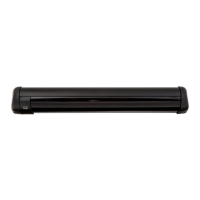
56.5(2 1/4")
275(10 3/4")
32(1 1/4")
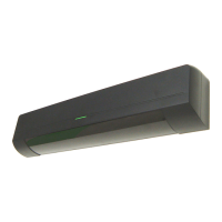
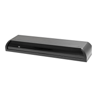
Model : OA-603
Cover color type
: Black , Slilver
Mounting Height : 2.0m (6’7”) to 2.5m (8’2”)
Detection Area : See the chart in “ADJUSTMENT”.
Detection Method : Active Infrared Reflection
(Presence Detection Type)
Detection Angle : Threshold Area ±5
(Inside & outside)
Adjustments :Swing Area ±5
(Inside & Outside)
Operation Indicator :Green : Stand-by
Blinking Red : Threshold Area Detection Active
Red : Swing Area Detection Active
Blinking Yellow :Learning
OUTER DIMENSIONS
SPECIFICATIONS
[mm (inch)]
248 (9 3/4”)
Operation Indicator
Insure proper setting of Mode switch #8 indicating Approach side or Swing side sensor.
ELITE
Swing Door
Door Mounting Sensor
(1)
(1)
(3)
(4)
(2)
(6) (7) (8)
(9)
(9)
(10)
MANUFACTURER'S STATEMENT
For ease of installation and proper operation read thru this manual (especially
) prior to installing and adjusting the sensor system.
Failure to read and follow the instructions in this manual may cause improper sensor operation resulting in serious injury or death.
This product is a non-contact activating switch intended for door mounted of an automatic door.
Do not use it for any other applications; otherwise proper operation and safety cannot be guaranteed.
1.Set door speeds and verify proper operation of door manufacturer’s equipment prior to applying power to the sensor system.
2.Do not install the sensor where it might be directly sprayed with rainwater.
3.Verify proper wiring prior to applying power to the sensor system to prevent damage to equipment.
4.When setting the sensor’s area pattern, make sure there is no traffic around the installation site.
5.Do not attempt to rebuild or repair sensor heads or control unit. Contact an address in this manual for replacement products.
6.Only use the sensor as specified in the supplied instructions.
7.Walk test the installation to verify operation is in compliance with all local laws, codes and standards of your country.
8.Upon completion of installation and adjustments, instruct the owner/operator on proper operation of the door and sensor system.
Identify any switches/breakers that will place the door out of service when unsafe or improper operation is identified.
Current Draw : 120mA Max
Response Time : < 0.3 second
Operating Temperature : -20
C
to +55 C (-4 F to +131 F)
Weight : 230g (8.2oz.)
Accessories : 1 Sensor Cable 0.2m(7”)
9 Mounting screws
1 Operation Manual
3 Mounting Template
(5)
WARNING
CAUTION
NOTE
Disregard of warning may cause the improper use causing death or serious injury of person.
Special attention for the setting and adjustment of section of this symbol is required.
Disregard of caution may cause the improper use causing injury of person or damage to
object.