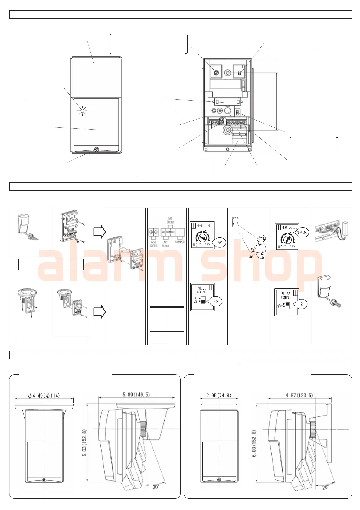
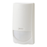
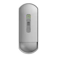
3.DESCRIPTION AND OPERATION
4.INSTALLATION PROCEDURE
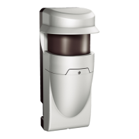
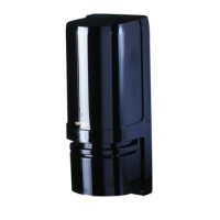
5.OPTIONAL BRACKETS
LED Indicater
Lens
cover screw
Day/Night Mode Adjustment
Inner Cover
Pulse Count Switch
Mount Pitch
3.28 Inches (83.5 mm)
Sensitivity Switch
Terminals
(Do not touch)
Sensor
Knockout
Multi-Level/Pet Alley
Adjustment Screw
Installation on wall
Installation on ceiling
1 3 NOTE ! 5 6 82
Loosen cover screw
and remove cover.
Pull wire throgh the
back of the detector.
If you have prob-
lems of wiring
through the back of
the detector, re-
move adjustment
screw and remove
the PCB from the
base.(see illus.)
Connect wires to
terminals, as shown.
Set the Day/Night
mode adjustment
to the “24HR” sett-
ing(DAY).
Set Pulse Count
to “TEST”mode.
Adjust sensitivity
setting (see sec-
tion 6-2 and 3).
Replace the cover
and supply power
to unit.
After the warmup
period is complete
(approx. 60 sec.) ,
conduct Walk Test.
The LED Indicator
lights when the
unit detects mov-
ing object.
Set the Day/Night mode
adjustment to the
NORMAL position(·).
( If night only operaton
is required , see sec-
tion 6-1)
Set Pulse Count to the
“2” position. ( see sec-
tion 6-1 and 2).
After wiring , pack the
provided sponge into
the opening between
each wires and the
knockout hole.
Select HIGH,
MEDIUM or
LOW
sensitivity(H,M,L).
Fasten cover with
the cover screw.
(see section 6-3)
Note ! Maximum mounting height is 8.3 ft (2.5m)
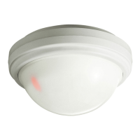
1. Ceiling Mount Bracket “CA-2C”
Adjust Horizontally : ±45° Adjust Vertically : 0° to 20° downward
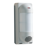
2. Multi-Angle Wall Mount Bracket “CA-1W”
Adjust Horizontally : ±45° Adjust Vertically : 0° to 20° downward
4
7 After conduct-
ing Walk Test.
Mirror
Photocell
Rubber packing
AWG18
(0.83 mm
2
)
2700ft
(820m)
AWG20
(0.52 mm
2
)
1700ft
(510m)
AWG22
(0.33 mm
2
)
1070ft
(320m)
wires size
inches(mm) inches(mm)
Selectable 3 position
( H, M, L).
Adjust Day/Night Mode according
to desired DAY/NIGHT
operating periods.
If angle adjustment is required, use the
optional “CA-1W” mounting bracket
Use optional ceiling mount bracket ”CA-2C”.
Power supply wires
should not exceed
the following
lengths.
LED lights
during detection.
Loosen screw and select.
For Muli-level : Lower position”M”
For Pet Alley : Upper position”P”
Standard”2”pluse or
“TEST” mode.
Cover
21
Install the bracket
“CA-2C” on ceiling
and pull wire.
Attach the LX-402/
802N to the bracket
and pull wire.