-9-
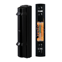
10°
10°
10°
10°
90°
90°
Horizontal alignment angle Vertical alignment angle
Caution
1
4
5
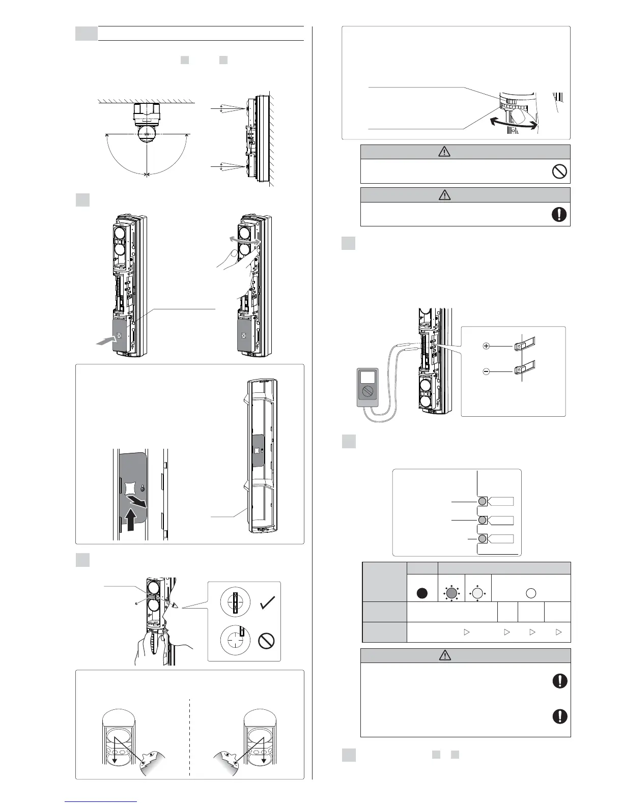
Optical alignment is an important procedure to increase reliability.
Be sure to take alignment step 1 through 5 described below to
attain the maximum level of the output through the monitor jack.
Level indicator
LED
Light
interrupted
Light received
Adjustment
level
Monitor jack
output
Realign Fair Good
Excellent
0 V 1.0 V 2.4 V 2.8 V
ON (Red)
Fast blink Slow blink
OFF
The Alarm indicator LED is a supporting tool for
easy alignment. Be sure to perform fine alignment
to ensure the maximum output level through the
monitor jack.
4-2
OPTICAL ALIGNMENT
3
After the alignment using the viewfinder, make adjustment
with the voltmeter for more accurate optical alignment.
Set the voltmeter range to 5 to 10 VDC.
After checking the receiving level of optical axis by using
the Level indicator LED, make sure to make fine
alignment for both transmitter and receiver with voltmeter
to achieve a monitor output level of "Excellent".
Adjust the horizontal and vertical angles while checking
the light receiving status by Alarm indicator LED on the
pairing receiver.
Perform rough alignment of the horizontal angle.
2
Look into the viewfinder and perform fine alignment of the
horizontal and vertical angles using the alignment dial.
Make the settings of 1 to 4 to the lower as well.
Caution
Low battery indicator LED
Alarm indicator LED
Level-ind
Alarm
Low Battery
Receiver
Level indicator LED
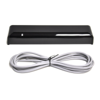
Insert the voltmeter's positive pin into
the positive terminal of the monitor
jack, and the negative pin into the
negative terminal.
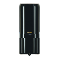
Mount a beam blocking plate to the lower
unit and then start optical alignment from
the upper unit.
Beam blocking plate is attached on the
back of the cover.
Return the beam blocking plate to the
cover after use.
Note>>
Cover
Do not look at strong light sources such as sunlight
through the viewfinder.
Warning
The Level indicator LED should only be used for
rough alignment, for fine alignment always use the
monitor jack output level.
< How to look into the viewfinder >
Left eye Right eye
From right side From left side
Note>>
Viewfinder
Beam blocking plate
Check the diagram below and perform fine alignment
for both horizontal alignment and vertical alignment.
Note>>
Turn the small dial for
horizontal alignment.
Turn the large dial for
vertical alignment.
- Clockwise: Upward
- Counterclockwise: Downward
 Loading...