6
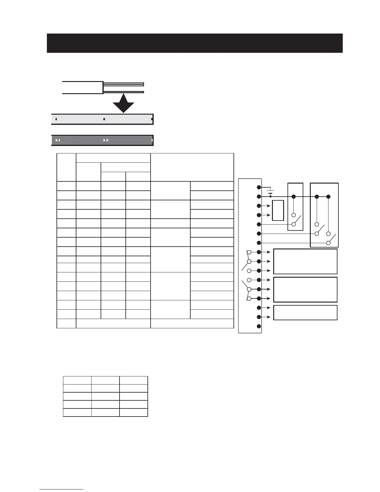
Wiring Diagram
BANK (1) (2)
1 OPEN OPEN
2 CLOSE OPEN
3 OPEN CLOSE
4 CLOSE CLOSE
.
.
.
15 pieces
Dot mark 1
Dot mark 2
No.
Output cable
Descriptions
Line
color
Dot mark
Color
Quantity
1 Pink Red 1
Power supply
12 to 24 VDC
2 Gray Black 1 GND
3 White Red 1
Analog output
4-20 mA
+
4 White Black 1
-
5 Pink Black 1
External trigger
Input
6 Gray Black 2
Bank switch
(1)
7 White Red 2 (2)
8 Yellow Red 1
Alarm output
H
N.C.
9 Gray Red 1 COM
10 Yellow Black 1 N.O.
11 Orange Red 1
Alarm output
L
N.O.
12 Gray Red 2 COM
13 Orange Black 1 N.C.
14 Orange Red 2
Digital output
Output
15 Orange Black 2 Input
16 *4 (Shielded cable)
-
Output cable
*1 Connect to the 4-20 mA input of an analog device.
Analog output allowable load 250Ω and analog output impedance 47 Ω
*2 External trigger: Switches on/off in the range from 2 to 5.
*3 Bank switch: Switches OPEN/CLOSE in the range from 2 to 6 or from 2 to 7 to select a bank.
*2 *3
c contact
300 mA/30 VDC or less
c contact
300 mA/30 VDC or less
Communication option -> PC
*1
*4 When you cut the output cables shorter, a shielded cable for reinforcement will come out. Cut the
shielded cable to prevent it from contacting with other cables.
* Cables not used should be cut so that they do not contact with other cables, and insulated with
adhesive tape or by other methods.
 Loading...