1. Always keep the detection window clean. If dirty, wipe the window with a damp cloth. Do not use any cleaner / solvent.
2. Do not wash the sensor with water.
3. Do not disassemble, rebuild or repair the sensor yourself, otherwise an electric shock may occur.
4. When the operation indicator blinks green, contact your installer or service engineer.
5. Always contact your installer or service engineer when changing the settings.
6. Do not paint the detection window.
WARNING
1. When turning the power ON, always walk-test the detection area to ensure the proper operation.
2. Do not place any objects that move or emit light in the detection area. (e.g. plant, illumination, etc.)
NOTE
INFORM BUILDING OWNER / OPERATOR OF THE FOLLOWING ITEMS
Contact your installer or service engineer.Sensor failure
Wrong wiring or connection failure. Check the wires and connector.
Wrong wiring or connection failure. Check the wiring.
None Wrong power supply voltage. Set to the stated voltage.
Wrong wiring or connection failure.
Fast
green
blinking
Dirty detection window Wipe the detection window with a damp cloth.
Do not use any cleaner or solvent.
Sensitivity is too low. Set the sensitivity higher.
Set AIR area width to "wide".
The detection area overlaps with the
door / header.
Adjust the detection area to "deep".
Door opens
when no one is
in the detection
area.
(ghosting)
Unstable
Door remains
open
Sudden change in the detection area Check Table1 dipswitch 1 to 4.
If the problem still persists, hard-reset the sensor.
(Turn the power OFF and ON again)
Slow
green
blinking
Check the wires and connector.
Remove highly reflecting objects from the detection
area or lower the sensitivity or change the area
depth angle for AIR area.
Door does not
open when a
person enters
the detection
area.
Unstable Wrong detection area positioning. Check ADJUSTMENTS 1, 2 ,3 & 4.
Sensitivity is too low. Set the sensitivity higher.
Short presence timer. Set the presence timer longer.
Proper
Proper
Dirty detection window. Wipe the detection window with a damp cloth.
Do not use any cleaner or solvent.
TROUBLESHOOTING
Proper
operation
Others Set
dipswitch 11 to ON.
Waterdrops on the detection window.
The detection area overlaps with
another sensor.
Detection area overlaps with door /
header.
Check Table1 dipswitch 5, 6.
Objects that move or emit light in the
detection area.
Remove the objects.
Sensitivity is too high. Set the sensitivity lower.
Installation mode is set to ON. Set dipswitch 16 to OFF.Yellow
Signal saturation (AIR)
Set dipswitch 7 and / or dipswitch 8 to ON.Raining or snowing(AIR)
Set dipswitch 9 and / or dipswitch 11 to ON.Raining or snowing(Microwave)
Wipe the detection window with a damp cloth.
Use the rain-cover (Separately available).
Adjust the detection area (AIR or Microwave) to
"deep".
Or set dipswitch 11 to ON.
FCC WARNING(For USA)
Changes or modifications not expressly approved by the party responsible for compliance could void the user's authority to
operate the equipment.
IC(For CANADA)
Operation is subject to the following two conditions:
(1) this device may not cause interference, and
(2) this device must accept any interference received, indluding interference that may cause undesired operation of the
device.
-NOTICE-
This equipment has been tested and found to comply with the limits for a Class B digital device, pursuant to part 15 of the
FCC Rules. These limits are designed to provide reasonable protection against harmful interference in a residential
installation.This equipment generates, uses and can radiate radio frequency energy and, if not installed and used in
accordance with the instructions, may cause harmful interference to radio communications. However, there is no guarantee
that interference will not occur in a particular installation. If this equipment does cause harmful interference to radio or
television reception, which can be determined by turning the equipment off and on, the user is encouraged to try to correct
the interference by one or more of the following measures:
- Reorient or relocate the receiving antenna
- Increase the separation between the equipment and receiver.
- Connect the equipment into an outlet on a circuit different from that to which the receiver is connected.
- Consult the dealer or an experienced radio/TV technician for help.
-NOTICE-
1.The antennas cannot be exchanged.
2.To comply with FCC RF exposure compliance requirements, aseparation distance of at least 20cm must be maintained
between the antenna of this device and all persons.
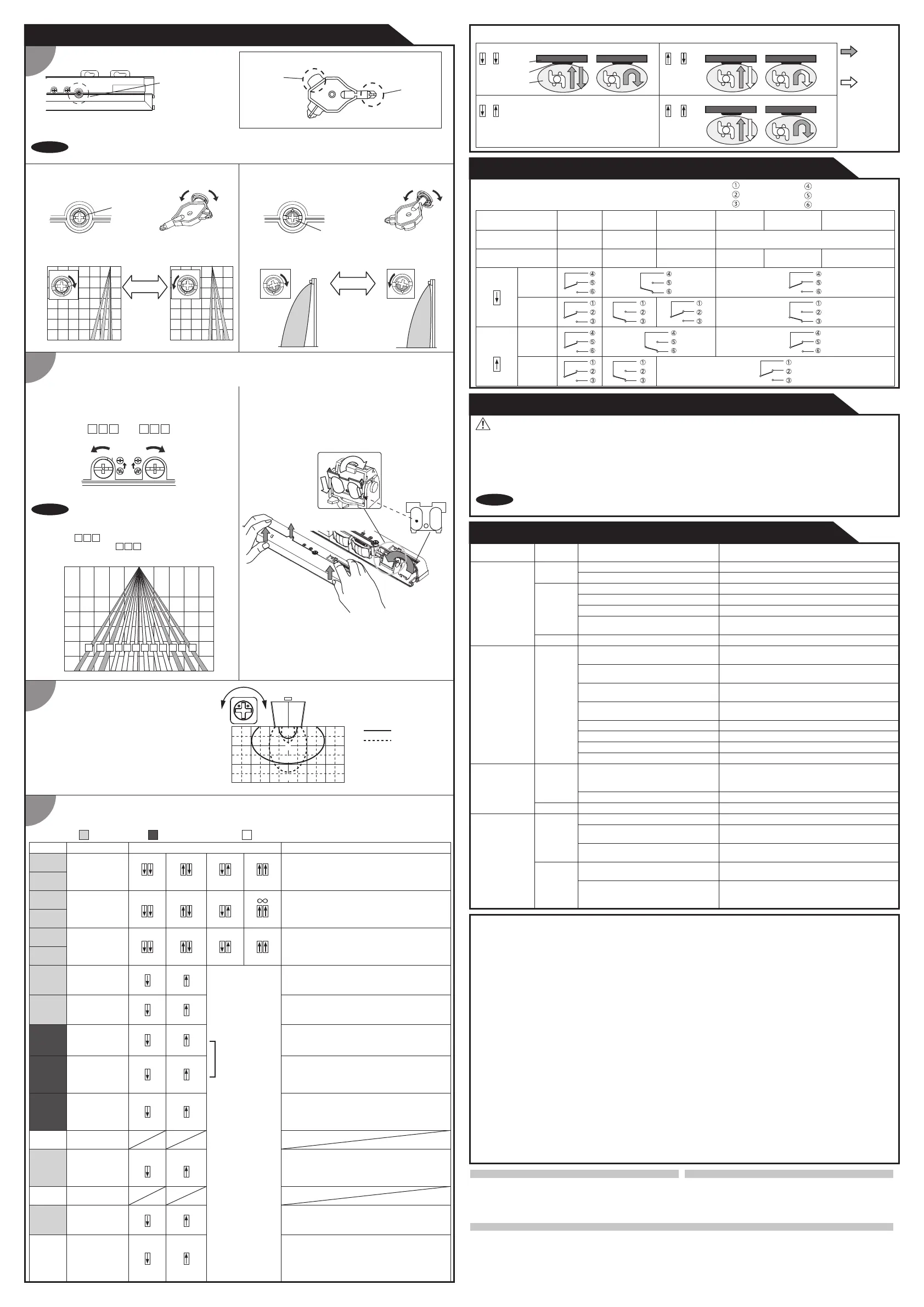
Check the operation in the operation mode according to the chart below.
CHECKING
: Detection
: Non-Detection
Detection
area
Bi-direction(Bi)
Bi-direction
Uni-direction(Uni)
Uni-direction with Auto caution mode
When dipswitch 9 is set to
Bi, Bi-direction mode is effective,
regardless of dipswitch 10 setting.
Bi
9
Bi
9
Uni
9
Uni
9
OFF
10
OFF
10
ON
10
ON
10
Sensor
Door
Table 2
1
ADJUSTMENTS
Area depth angle adjustment
Area adjustment tool
A
B
Red
Blue
Depth angle adjustment screw
for the AIR area
Depth angle adjustment screw
for the microwave area
Use the area adjustment tool (A) as shown above
to change the area depth angle.
3
1-1AIR adjustment
1-2 Microwave adjustment
Depth angle
adjustment screw
Shallow Deep
Dipswitch settings
When adjusting the 2nd row close to the door,
follow Table1 dipswitch16 for the easier adjustment.
Make sure that the detection area does not overlap with the door / header, and there is no highly reflecting
object near the detection area otherwise ghosting / signal saturation may occur.
NOTE
NOTE
4
Shallow Deep
When setting the detection area width, make
sure to turn the adjustment screws until it
clicks.
cannot be eliminated separately,
neither can
1 2 3
10 11 12
2
Area width adjustment
2-1 AIR adjustment
Width adjustment screws
Narrow
Wide
Eliminated
Eliminated
1 2 3 10 11 12
To adjust the AIR detection area width, use the
adjustment screws as shown in the picture below.
2-2 Microwave adjustment
Use the area adjustment tool (B) as shown above
to change the area depth angle.
ShallowDeep
L H
H
L
Top view
H
L
[mm]
AIR settings Microwave settings Other settings
Table1
Adjust the microwave detection area
with potentiometer.
Turning it clockwise increases the
sensitivity and turning counterclockwise
lowers the sensitivity.
ShallowDeep
0
[mm]
[mm]
Microwave sensitivity
OPTEX CO., LTD.
Manufacturer
5-8-12 Ogoto Otsu 520-0101, Japan
TEL.: +81(0)77 579 8700 FAX.: +81(0)77 579 7030
WEBSITE: www.optex.net
OPTEX Technologies B.V.
European Subsidiary
Henricuskade 17, 2497 NB The Hague, The Netherlands
TEL.: +31(0)70 419 41 00 FAX.: +31(0)70 317 73 21
E-MAIL: info@optex.eu WEBSITE: www.optex.eu
East coast office
8510 McAlpines Park Drive, Suite 108
Charlotte, NC 28211 U.S.A.
TEL.: +1-800-877-6656 FAX.: +1(704)365-0818
WEBSITE: www.ot-inc.com
OPTEX INCORPORATED
North and South America Subsidiary
18730 S. Wilmington Avenue, Suite 100 Rancho
Dominguez CA 90220 U.S.A
TEL.: +1-800-877-6656 FAX.: +1(310)898-1098
WEBSITE: www.ot-inc.com
2000
3000
0
2000
3000
2000 1000 0 2000 1000 0
To adjust the microwave detection area width, use the
narrow lens referring to the following procedures.
For detection area, See DETECTION AREA in the
front page.
Front view
[mm]
1 2 3 4 5 6 7
8
9 10 11
12
0
2000
3000
02000 20001000 1000
Narrow lens
3
4
1. Remove screw
2. Press with thumbs
and lift detection
window up.
4. Push it until it
clicks.
3. Set narrow lens in
front of antenna.
0
0
1000 1000 200020003000 3000
1000
2000
3000
Mounting height : 2.2m
Vertical adjustment : +35°
Wide area
Narrow area
Sensitivity
Function
Setting Comment
2.0 to 3.0m
Low
21
Middle
2.0 to 3.0m
21
Presence
timer
30sec.
43
180sec.
43
Frequency
Setting2
Snow mode
Rain
Rain mode
Direction
Auto caution
Setting1
65 65
Normal
7
7
Normal
8
Snow
8
Bi
9
Uni
9
OFF
10
ON
10
Dipswitch
1
Dipswitch
2
Dipswitch
3
Dipswitch
4
Dipswitch
5
Dipswitch
6
Dipswitch
7
Dipswitch
8
Dipswitch
9
Dipswitch
10
High S-High
2.5 to 3.2m 3.0 to 3.5m
21
21
Set the sensitivity according to the mounting
height. Values below dipswitch are reference
only.
600sec.
43 43
All rows have the presence detection function.
The presence timer can be selected from
4 settings.
Setting4Setting3
65 65
* Please refer to
Table 2 for the
details.
When using more than one sensor close to
each other, set the frequency different for each
sensor.
Set this switch to Rain if the sensor is used in
a region with a lot of rain.
Set this switch to Snow if the sensor is used in
a region with snow or a lot of insects.
When dipswitch 9 is set to uni-directional, this
setting enables the door to close earlier when
a person walks away from the door.
When dipswitch 10 is set to ON, a person
wavering in the activation detection area can be
detected. This is only effective when dipswitch 9
is set to uni-directional.
Immunity
OFF
11
ON
11
Dipswitch
11
Set dipswitch 11 to ON when the sensor
operates by itself (ghosting).
When dipswitch 11 is set to ON the actual
detection area may occur smaller.
For future use
AIR output
Safety
13
Safety +
Activation
13
Dipswitch
12
Dipswitch
13
When dipswitch 13 is ON, the sensor outputs
safety and activation simultaneously.
Installation
mode
OFF
16
ON
16
BLUEZONE
OFF
15
ON
15
For future use
Dipswitch
16
Dipswitch
15
Dipswitch
14
When dipswitch 15 is set to ON, the
BLUEZONE (1st row) is active and looks
through the threshold.
Set dipswitch 16 to ON to adjust the 2nd row.
After setting the row switch dipswitch 16 to OFF.
During the installation mode only the 2nd row
remains active and the operation indicator
shows yellow.
: COM.
: N.O.
: N.C.
White
Yellow
Green
: COM.
: N.O.
: N.C.
White Str.
Yellow Str.
Green Str.
Status
Green
Motion
detection active
Blue
Motion / Presence
detection active
Entry
Outside of
detection area
Entry into
microwave area
Entry into
3rd row
Entry into
BLUEZONE(1st row)
Orange Red
Stand-by
Operation indicator
Power OFF
-
None
Safety
output
Activation
output
Safety
output
Activation
output
Safety
13
Safety
+
Activation
13
Red blinking
Entry into
2nd row
Door operation
Operation
indicator
Possible cause
Possible countermeasures
 Loading...