25
The belt speeds given in Table 3.4 should not be exceeded for the
standard drives. For belt speeds close to these maximum values,
increased belt tension is necessary.
3.3 ZRM/ZRP belt selection graphs
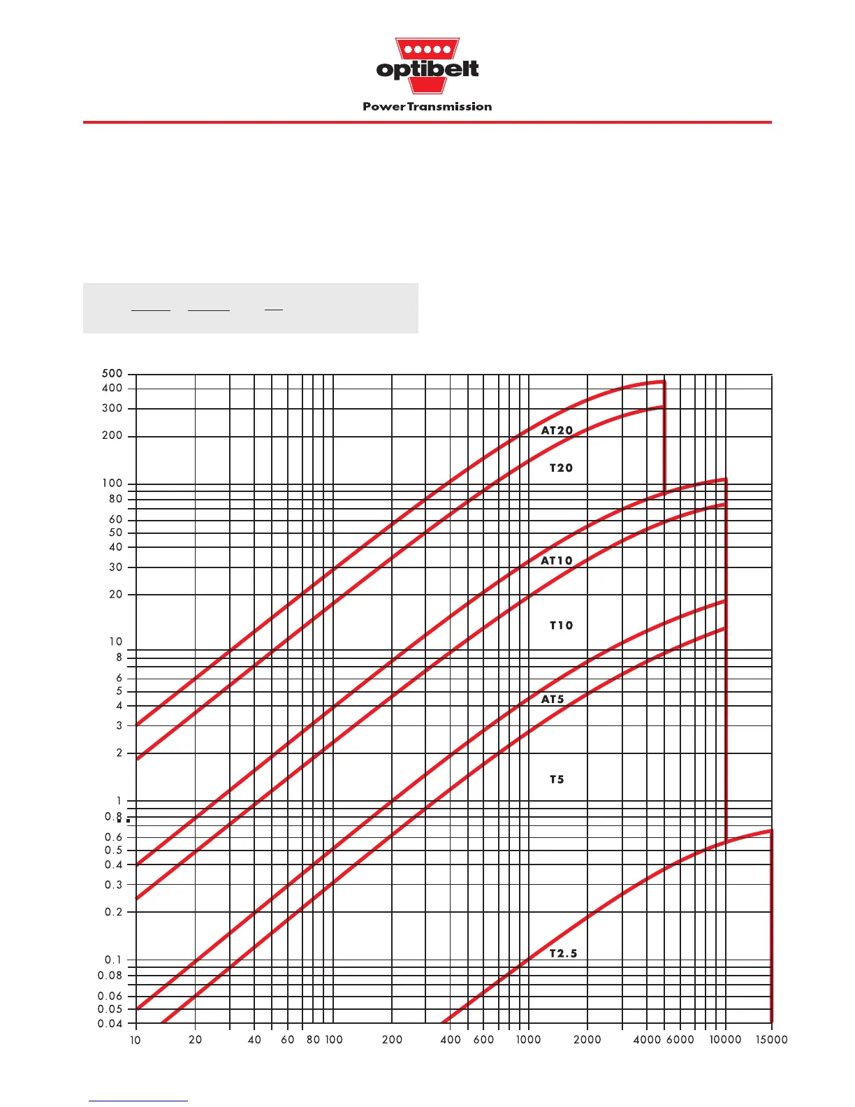
Power rating graphs for section selection and maximum belt speeds for
optibelt
ZRM/ZRP timing belts, Z
emax
= 12
The smaller of the two drive pulleys is used for the calculation
irrespective of whether it is used as a driver or a driven pulley.
The values given for the transmissible power P
spez
(W/cm) in Table
3.5, page 25 are based on one tooth in mesh, a 10 mm timing belt
width and one tooth of the small pulley.
These values are not based on the belt tension cord strength, but
on the shear strength of the teeth based on the particular mode of
operation.
Speed of the small pulley n
k
(min
-1
) →
Design power P
B
(kW) →
Graph 3.2: ZRM power ranges
v= =
d
w1
· n
1
19100
d
w2
· n
2
19100
( )
m
s


 To Next Page