24
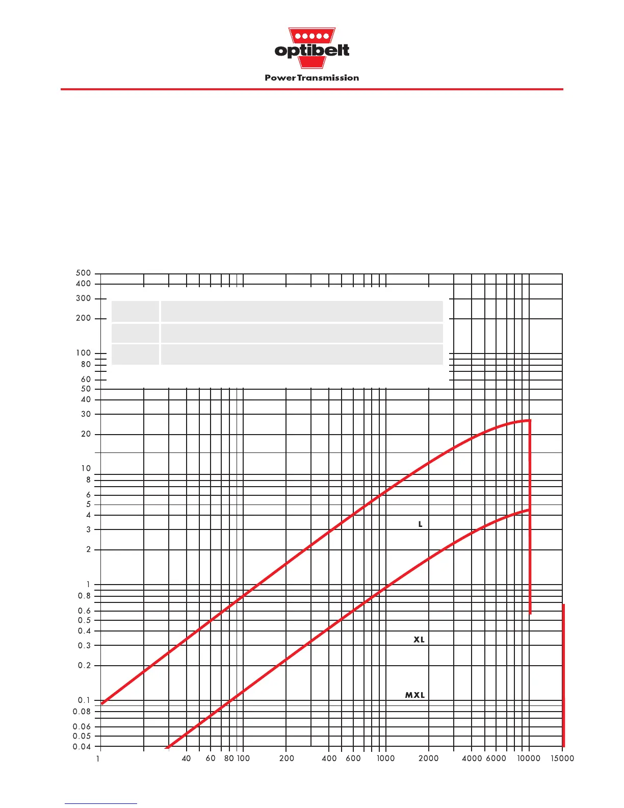
3.3 ZRM/ZRP belt selection graphs
Power rating graphs for section selection and maximum belt speeds for
optibelt
ZRM/ZRP timing belts, Z
emax
= 12
The maximum belt speeds for the individual timing belt sections in
these graphs are based on pulleys with 60 teeth, at least 12 of
which are in mesh. In addition each maximum width is based on
a combination of standard timing belts and standard pulleys (see
Table 3.4).
Wider belts can be used with special pulleys allowing increased
power transmission.
Specifying smaller pulley diameters, a smaller number of teeth in
mesh or narrower belts, will reduce the maximum power limits
proportionally.
Design power P
B
(kW) →
Speed of the small pulley n
k
(min
-1
) →
Graph 3.1: ZRP power ranges
Section
MXL* XL L T2.5 T5(D) T 10(D) T 20*(D)* AT 5* AT10* AT20*
b
St
** (mm) 6.4 9.5 25.4 6 25 50 100 25 50 100
v
max
(m/s) 80 60 40 80 60 40 30 60 40 30
* Non stock
** Maximum width using a standard timing belt and a standard pulley
Table 3.4: Maximum standard width and speed


 To Next Page