44
Minimum diameter and clamping length
Pulley diameters should be maintained at or above minimum to
avoid shortening belt life.
Table 5.4: Minimum diameter and the length to be clamped in
clamping plates
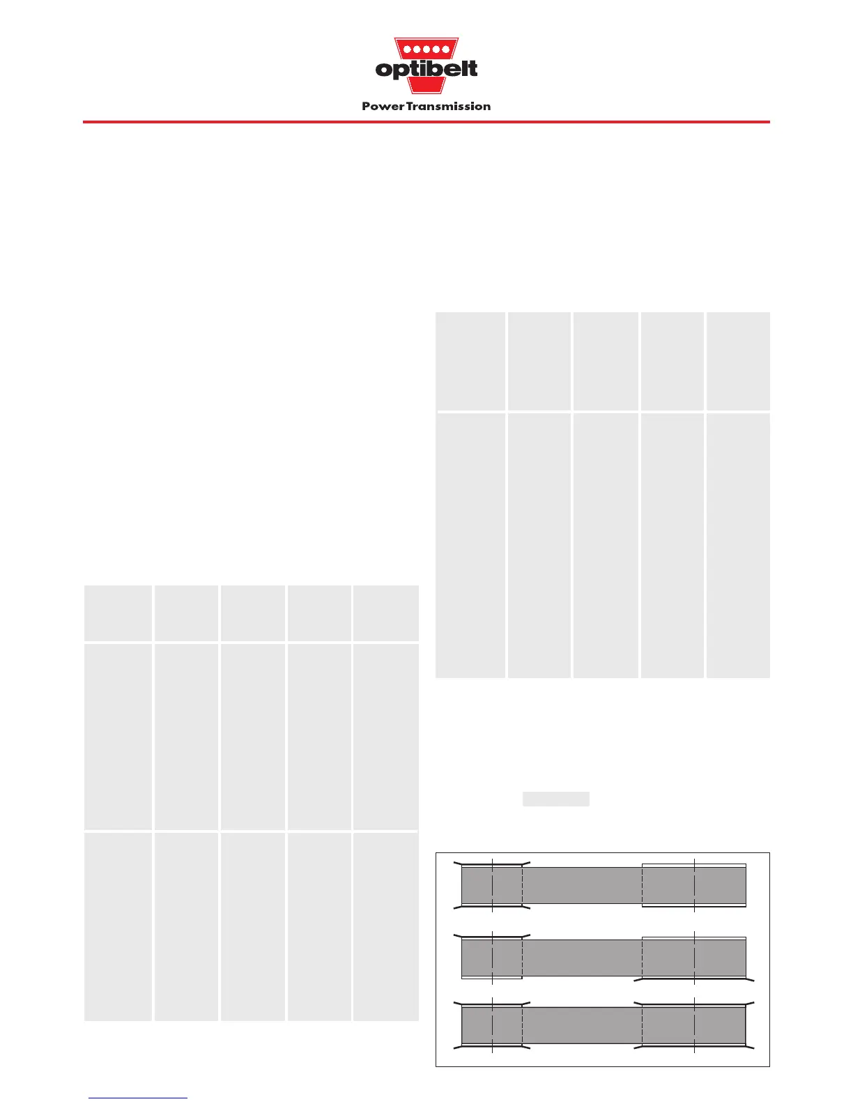
Flanged pulleys
The timing belt must be controlled on both sides to prevent it running
off the pulleys. The smallest pulley on the drive should always be
flanged on both sides. When both pulleys are flanged on one side
they should be arranged as shown in 5.1 so that the flanges control
both sides of the belt.
With centres a > 8 d
wk
, all pulleys should be have
flanges on both sides.
Figure 5.1: Arrangement of flanges
Standard timing belt pulleys and timing belt bars
The pulleys are produced to standard sizes (see Table 5.6,
page 48). We recommend the use of standard pulleys in order to
minimise cost and delivery times. If this is not possible for reasons
of environmental conditions or design, special pulleys can be
supplied to drawing.
Pulleys of the standard range are pilot bored and can on request
be finish bored and keywayed.
As can be seen from Table 5.3, pulleys of steel or cast iron as
alternative to the pilot bored version are suitable for use with taper
bushes. These standard pulleys are provided with a taper bore for
the appropriate taper bush. The taper bush system allows speedy
delivery for standard pulleys with a specified shaft diameter as well
as simple replacement of a worn pulley.
Timing belt bar availability should be checked separately.
For further information on plastic pulleys, see the pulley range on
pages 76 and 77.
Table 5.3: Standard pulleys and timing belt bars
1
) Material dependent on diameter
2
) Small diameters not pilot bored
3
) Timing belt bars are not bored at all
5 Design Hints, Dimensions and Tolerances
5.2 Standard pulleys, flanged pulleys, idlers, clamping plates and
minimum numbers of teeth
MXL 10 6.47 15 —
XL 10 16.17 30 8
L 10 30.32 60 6
H 14 56.60 100 6
XH 18 127.34 180 6
T2.5 10 7.96 15 —
T5 10 15.92 30 8
T10 12 38.20 60 6
T20 15 95.49 120 6
AT5 12 19.10 60 8
AT10 15 47.75 120 6
AT20 18 114.59 180 6
5M 14 21.14 60 6
8M 22 56.02 120 6
14M 28 124.78 180 6
Min.
number
of teeth
on pulley
z
k
Small pulley with flanges on both sides
Flanges on alternate sides
Both pulleys with flanges on both sides
XL
1
)
L
H
XH
5M
8M
14M
3
)
3
)
•
•
•
•
•
•
•
•
•
•
•
•
lairetaMgnimiT
yellup
noitces
gnimiT
rab
noitces
toliP
erob
repaT
hsub
cast iron,
steel,
aluminium
Range
pages
54 to 79
Aluminium;
Range
pages
80 to 88
XL
1
)
T2.5
2
)
T5
T10
AT5
AT10
XL
1
)
L
MXL
XL
1
)
T2.5
T5
T10
●●
●
Section Min.
pitch
diameter
of pulley
d
w
(mm)
Min.
diameter
of idler
Min.
length
clamped
by
plate
(teeth)
except for
XL
section