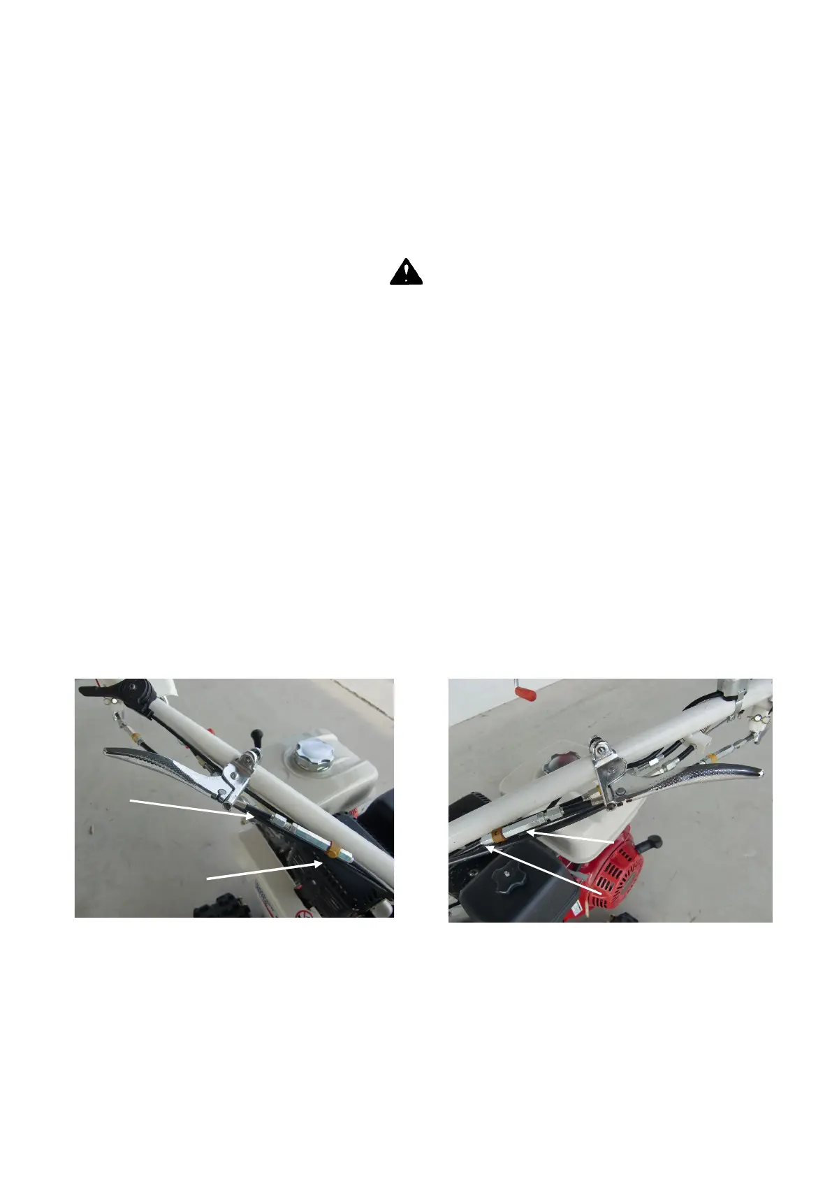
• If the blade does not stop when the blade lever is released, adjust the tension wire as follow : unscrew
the locking screw (A, Figure 19) and unscrew the nut (B, Figure 19). Try the machine again. Perform
the adjustment again if needed. When the adjustment is performed screw the locking screw (A, Figure
19) on the nut (B, Figure 19).
• If the blade does not move when transmission lever is pressed, adjust the tension wire as follow :
unscrew the locking screw (A, Figure 19) and after screw the nut (B, Figure 19). Try the machine again.
Perform the adjustment again if needed. When the adjustment is performed screw the locking screw
(A, Figure 19) on the nut (B, Figure 19).
Blade brake is connected with the blade wire. Check if the blade brake works correctly when
adjusting blade wire control.
Direction wires :
If the wheel is not free(HR531/662/) or not locked(HR672/812) with side clutch lever engaged, adjut as
follows:
•Uscrew locking nut (E, Figures 18,19).
•Screw or unscrew the nuts F .
•Try the machine.
•Adjust again if it is necessary.
•Screw the locking nut “E” on the adjusting nuts “F”.
Handlebar Control wire adjustment
If the handlebar control doesn’t work correctly, adjust as follow :
- If it is difficult to free the handlebar, unscrew the nut (A, Figure 20,21), then screw the nut B to increase
the wire tension. When the adjustment has been performed, rescrew the nut A.
- If the handlebar doesn’t lock properly, unscrew the nut (A, Figure 20,21), then uncrew the nut A to
decrease the wire tension. When the adjustment has been performed, rescrew the nut B.
¥