2
GB
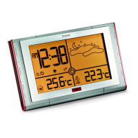
MODE WINDOW
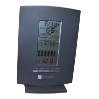
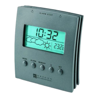
Displays the current time and date
ALARM ICON "
AL
"
Appears when the alarm is displayed
ALARM ON ICON
Appears when the alarm is activated
RIGHT PANEL AND CONTROL BUTTONS
The front left panel has dual purposes. First, it can be used as a
support when the unit is positioned on a flat horizontal sur-
face. This panel houses five commonly used control buttons.
Placed vertically along the right lower section of the panel,
they are used to access or input information.
TEMPERATURE (THERMO) BUTTON
Sets the indoor or outdoor-remote temperature mode
MEMORY BUTTON
Sets minimum and maximum temperature readings, indoor
relative humidity readings, and erases memory data
HISTORY BUTTON
Used to obtain previous air pressure readings
UP ( ) DOWN ( ) BUTTON
Sets the increase or decrease in the value of a setting, or to scan
moon phase data.
ALARM OFF / ON BUTTON
Displays the alarm time or sets the alarm status
MODE BUTTON
Changes the display mode of the clock, alters time/date
data, and altitude
OTHER SWITCHES AND CONTROLS
SNOOZE / LIGHT BAR
Activates the snooze function, functions to turn on the backlight
°C/°F SLIDE SWITCH
Selects between Centigrade (°C ) or Fahrenheit (°F) display
PRESSURE UNIT SLIDE SWITCH
Selects between mb/hPa or inHg display
BACK PANELS
BATTERY COMPARTMENT
Accommodates four UM-3 or “AA” size batteries
RESET SLOT
Resets the unit by returning all setting to their default values
MAIN FEATURES :
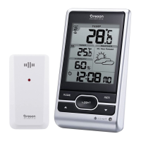
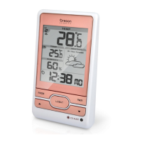
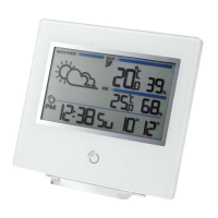
REMOTE SENSOR UNIT
The remote sensor is an independent component. It comes with a
wall-mount holder and removable table stand.
LCD
The LCD window, located on the front upper section of the
remote unit, displays the current temperature reading
LED INDICATOR
A small red light located under the LCD window indicates when
the unit is transmitting a signal
°C/°F SLIDE SWITCH
Located inside the battery compartment, this switch enables
the a selection between Centigrade (°C) or Fahrenheit (°F)
display
RESET SLOT
Also located inside the battery compartment, this slot returns
all settings to default settings
BATTERY COMPARTMENT
Accommodates two UM-4 or “AAA” size batteries
WALL-MOUNT HOLDER
A plastic device for mounting the remote sensor to a wall.
REMOVABLE TABLE STAND
A removable stand for mounting the remote sensor on a flat
horizontal surface
Note: Also located inside the battery compartment is a channel
switch. The channel switch is used when there is more than one
remote sensor. For use of one remote sensor, use the factory
setting of one.
BEFORE YOU BEGIN
For best operation:
1. Insert batteries for the remote unit first. Then proceed with
inserting the batteries for the main unit.
2. Position the remote unit and the main unit within effective
transmission range. In usual circumstances, the effective range
is 30 meters.
 Loading...