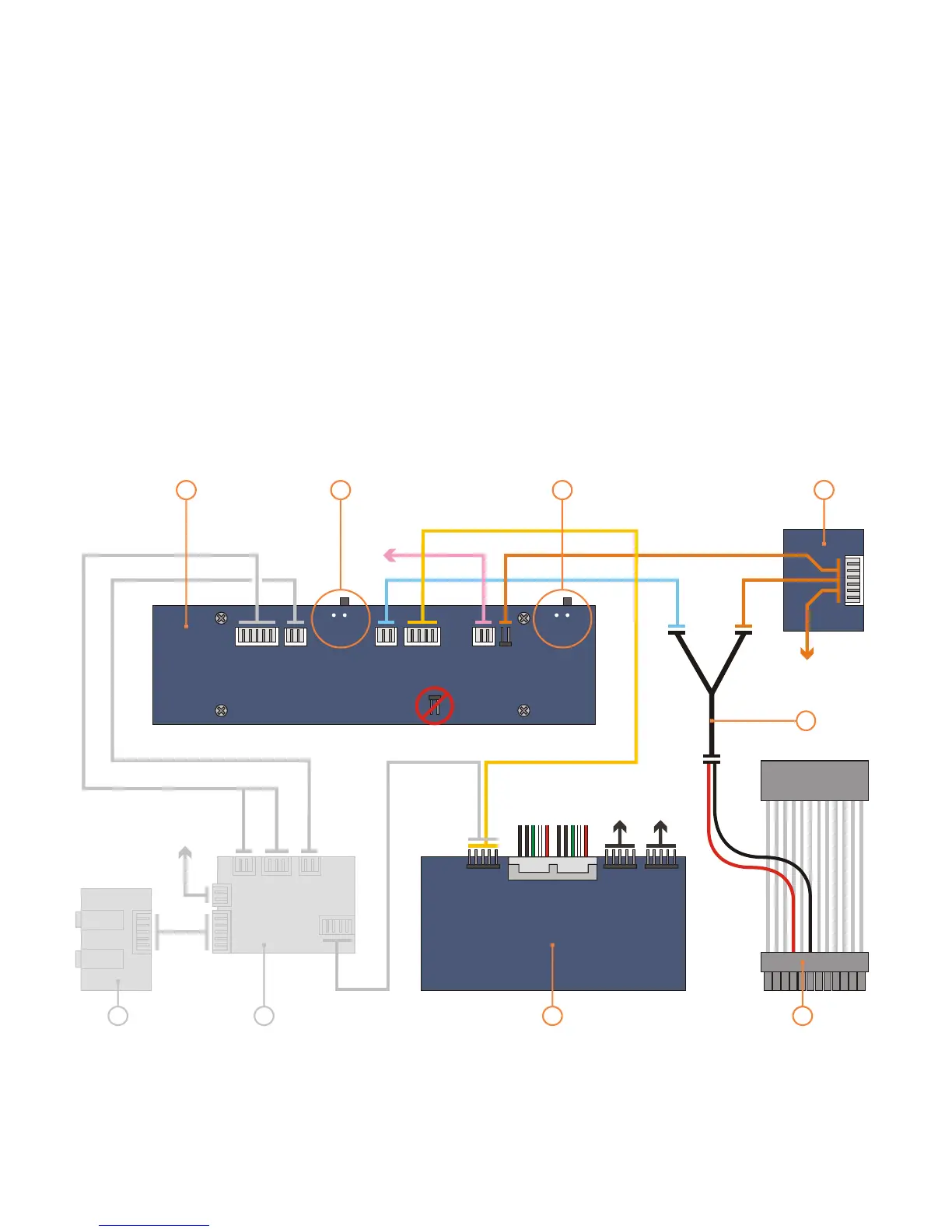
PCB/cable reference diagram
This is a general overview illustrating
how the internal PCBs interconnect.
. The VFD should be
switched to ‘IR Trans’ by default, which
uses The LED
switch toggles this feedback feature ON
(2) and OFF (1). Please refer to your
motherboard manual for the location of
the correct ports and header pins.
Grey
PCBs/cables indicate they come as part
of an optional IR kit
the built in IR controller.
1 - VFD/IR Module (VF210)
2 - [VFD] IR selector switch (IR Trans is default)
3 - [VFD] LED switch (IR Trans: 2=ON 1=OFF)
4 - Main power button PCB
5 - Standby power ‘Y’ cable
8 - Card reader/USB hub PCB
9 - Standby ATX power cable
6 - Philips IR blaster output (optional)
7 - Philips IR control PCB (optional)
MOLEX
[to PSU]
M/B
[1394]
M/B
[audio]
M/B [2xUSB]
M/B
1
8
7
6
9
4
5
IR TRANS
PHILLIPS
M/B [ACPI]
(optional)
2 1
2
3
13
 Loading...