15
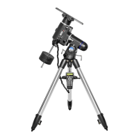
8. Technical Specifications
Mount: German equatorial
Tripod: Steel
Weight: 54 lbs.
Counterweights: Quantity 2, 11 lbs. each
Polar axis latitude adjustment: 10° to 65°
Polar axis finder scope: Included, illuminator
built into mount
Motor drives: Dual-axis, GoTo comput-
erized, internally housed
Operation: N o r t h e r n o r
Southern
hemisphere
Autoguiding rates: 1.25X / 1.5X / 1.75X / 2X
sidereal rate
Power requirrement: 12V DC, 2A (tip posi-
tive)
Motor type and resolution: Microstep driven 1.8°
stepper motors
Resolution: 0.144 arc sec (or
9,024,000 steps/rev)
Slew speeds: Rate 0 = 1.5X
Rate 1 = 2X
Rate 2 = 8X
Rate 3 = 16X
Rate 4 = 32X
Rate 5 = 64X
Rate 6 = 400X
Rate 7 = 500X
Rate 8 = 600X
Rate 9 = 800X (3.4°/sec)
Gear ratio: 705
Tracking rates: Sidereal (default)
lunar, solar, PEC +
sidereal.
Tracking modes: R.A. tracking
Alignment method: One-star alignment, two-
star alignment, three-star
alignment
Database: 25 user-defined objects,
complete M, NGC. and
IC catalogs, total 13,436
objects.
Pointing accuracy: Up to 1 arcminute with
cone error calibration, up
to 15 arcminutes without
cone error calibration
This device complies with Part 15 of the FCC Rules. Operation
is subject to the following two conditions: (1) this device nay
not cause harmful interference, and (2) this device must
accept any interference received, including interference that
may cause undesired operation.
Changes of modifications not expressly approved by the party
responsible for compliance could void the user’s authority to
operate the equipment.
Note: This equipment has been tested and found to comply
with the limits for a Class B digital device, pursuant to Part
15 of the FCC Rules. These limits are designed to provide
reasonable protection against harmful interference in a resi-
dential installation. This equipment generates, uses and
can radiate radio frequency energy and, if not installed and
used in accordance with the instructions, may cause harm-
ful interference to radio communications. However, there is
no guarantee that interference will no occur in a particular
installation. If this equipment does cause harmful interference
to radio or television reception, which can be determined by
turning the equipment off and on, the user is encouraged to
try to correct the interference by one or more of the following
measures:
-Reorient or relocate the receiving antenna.
-Increase the separation between the equipment and
receiver.
-Connect the equipment into an output on a circuit different
from that to which the receiver in connected.
-Consult the dealer or an experienced radio/TV technician
for help.
A shielded cable must be used when connecting a peripheral
to the serial ports.
Appendix A: Enhancing the
Precision
The Atlas EQ-G produces pointing accuracy and tracking
accuracy adequate for most applications. If higher
precision is required, “cone” error calibration may be neces-
sary.
Cone Error Calibration
“Cone” error is a common inaccuracy found on all German
equatorial mount designs. Cone error results from the optical
axis of the telescope not being aligned to the R.A. axis of the
mount. This affects the pointing accuracy of the Atlas EQ-G.
Three-star alignment automatically compensates for some of
the “cone” error, but pointing accuracy will be optimized by
mechanically minimizing the “cone” error. The following cali-
bration procedure should be performed before the initial use
of the telescope and periodically thereafter to ensure peak
accuracy.
Testing for Cone Error
This test is performed at night using two bright stars located
on opposite hemispheres of the night sky. Confirm that the
 Loading...