Do you have a question about the Orion Corale Series CS500.5 and is the answer not in the manual?
Details how the manual is designed to answer product questions and provides contact info.
Warns about hearing loss from high sound pressure levels and recommends hearing protection.
Prompts users to record serial number, model, purchase date, and company for reference.
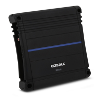
Lists the items included with the COBALT Power Amplifier and Reference Manual.
Details parts and labor warranty periods based on dealer purchase and installation.
Lists conditions and situations not covered by the warranty, like misuse or unauthorized modification.
Provides detailed technical specifications for the CS 500.5 amplifier's power output and distortion.
Details the low-pass and high-pass crossover frequency ranges and boost features.
Lists general physical dimensions (L x W x H) for the amplifier.
Adjusts input gain to match amplifier to different signal levels from the head unit.
Adjusts the high-pass crossover frequency from 30Hz to 1kHz for front channels.
Adjusts the low-pass crossover frequency from 30Hz to 250Hz for front channels.
Determines if crossover operates in high-pass, full-range, or low-pass mode for front channels.
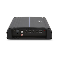
Removable plug accepting up to 8ga power and ground connections.
Removable plug accepting up to 16 gauge speaker wire.
Accepts line level signal from aftermarket head units or ORION accessories.
Steps to match amplifier signal level to head unit output, minimizing noise and preventing overload.
Boosts low-end bass centered at 40Hz by 0-12dB for improved bass response.
Adjusts low-pass frequency (30Hz-250Hz) for subwoofers, using chart for exact points.
Selects crossover mode (high-pass, low-pass, full range) for front and rear channels independently.
Specifies the amplifier model and its required fuse size.
Diagram shows connection to the vehicle's battery for power supply.
Instructions for safely connecting the positive power wire, including fusing near the battery.
Steps for creating a secure ground connection close to the amplifier for optimal performance.
Details how to connect the remote turn-on wire from the head unit to the amplifier.
Specifies that speaker connectors accept up to 16 gauge wire.
Advises setting XBC12 to 0dB and high-pass crossover above speaker's lower frequency range.
States minimum impedance for stereo (2 Ohms) and mono (4 Ohms) subwoofer channels.
Recommends setting subwoofer crossover to low pass to block high frequencies.
Suggests setting XBC12 per listening preference and low-pass on subwoofer channels.
Specifies minimum impedance for subwoofer channels (4 Ohms mono) and stereo channels (2 Ohms stereo).
Recommends low-pass for subwoofer channels and high-pass for stereo channels.
States the lowest recommended impedance for each bridged channel is 4 Ohms.
Crossover settings will be independently adjusted for each channel.
Use capacitors to block lower frequencies for midrange drivers.
Use a coil on the subwoofer to block higher frequencies.
Lowest recommended stereo impedance is 2 Ohms.
Set XBC12 to 0dB to prevent damage to midrange speakers.
Lists essential and helpful tools required for amplifier installation.
Guidance for mounting in passenger compartment, ensuring adequate ventilation and clearance.
Advice for trunk mounting, recommending vertical cooling fins for optimal cooling.
Advises against mounting in the engine compartment due to harsh environmental conditions.
Warning to avoid cutting or drilling into vehicle's gas, fuel, brake, vacuum, or electrical lines.
Instruction to disconnect the battery ground wire before making power connections to prevent shorts.
Emphasizes securely mounting the amplifier to prevent damage or injury in case of an accident.
Mandates fusing the +12V power supply wire close to the battery terminal, ideally within 18 inches.
Fourth step involves pre-drilling mounting holes, advising caution for obstructions.
Fifth step is to securely mount the amplifier on a flat surface, avoiding twisting the chassis.
Eleventh step involves setting crossover and signal routing configurations.
Final step to install fuse, test system, and warns against exceeding recommended fuse size.
Fourth step is to set source unit volume to highest undistorted level for tuning.
Fifth step adjusts midrange/tweeter level to just before distortion for undistorted output.
Sixth step adjusts tweeter level to just before distortion for undistorted output.
Seventh step involves fine-tuning crossover settings and output levels for midrange and tweeters.
Ninth step is to set midrange/tweeter levels for optimal front/rear balance.
Tenth step adjusts woofer level to just before distortion for undistorted output.
Eleventh step fine-tunes crossover and output levels between satellite speakers and woofers.
Final step encourages the user to enjoy the installed sound system.
Addresses issues like no remote voltage, blown fuse, or disconnected wires causing no output.
Troubleshoots audio cycling due to thermal protection, poor input, or loose power connections.
Covers causes like incorrect gain, low impedance, shorted wires, or poor connections.
Addresses issues like incorrect crossover settings, wrong speaker wiring, or low impedance.
Troubleshoots battery fuse blowing due to shorted power wires or incorrect wiring.
Covers amplifier fuse blowing caused by low impedance, excessive current draw, or wrong fuse size.
| Channels | 5 |
|---|---|
| Frequency Response | 20Hz - 20kHz |
| THD | <0.05% |
| S/N Ratio | >90dB |
| Input Sensitivity | 200mV - 6V |
| Crossover Frequency | 50Hz - 250Hz |
| Bass Boost | 0dB - 12dB |