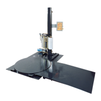
MACHINE INSTALLATION
After the visual inspection has been completed, the electrical power and the compressed air
shall be connected as specified on the diagrams supplied with the machine.
An electrical diagram is provided with each machine in the envelope attached to the panel
box.
ASSEMBLY PROCEDURE
The structural frames of the machine have to be installed on a leveled floor.
Locate the main wrapper section into its final position, keeping the tower assembly* away
from any traffic.
The wrapper mainframe section must be bolted to the floor by the 1/2” concrete floor
anchors (leg & shield or expandable type).
Any wiring that has been disconnected to facilitate transport is marked with a number
located on the junction box to which the wiring must be reconnected. Any wire run that
appears too short or long may indicate that the position of the mechanical components is
incorrect. Verify the status of all assemblies before proceeding.
* The tower deviation from vertical must not exceed 1/4” on the distance of 10 feet (angle: 0
degrees 6’).
CONTROL PANEL
In the case of the free standing panel (console) place it adjacent to the system and anchor
firmly to the floor. Connect the liquid tight (rigid conduit) to the main junction box located on
the wrapper main frame next to the tower.

 Loading...