Page 20 / 36
Hartley and Sugden
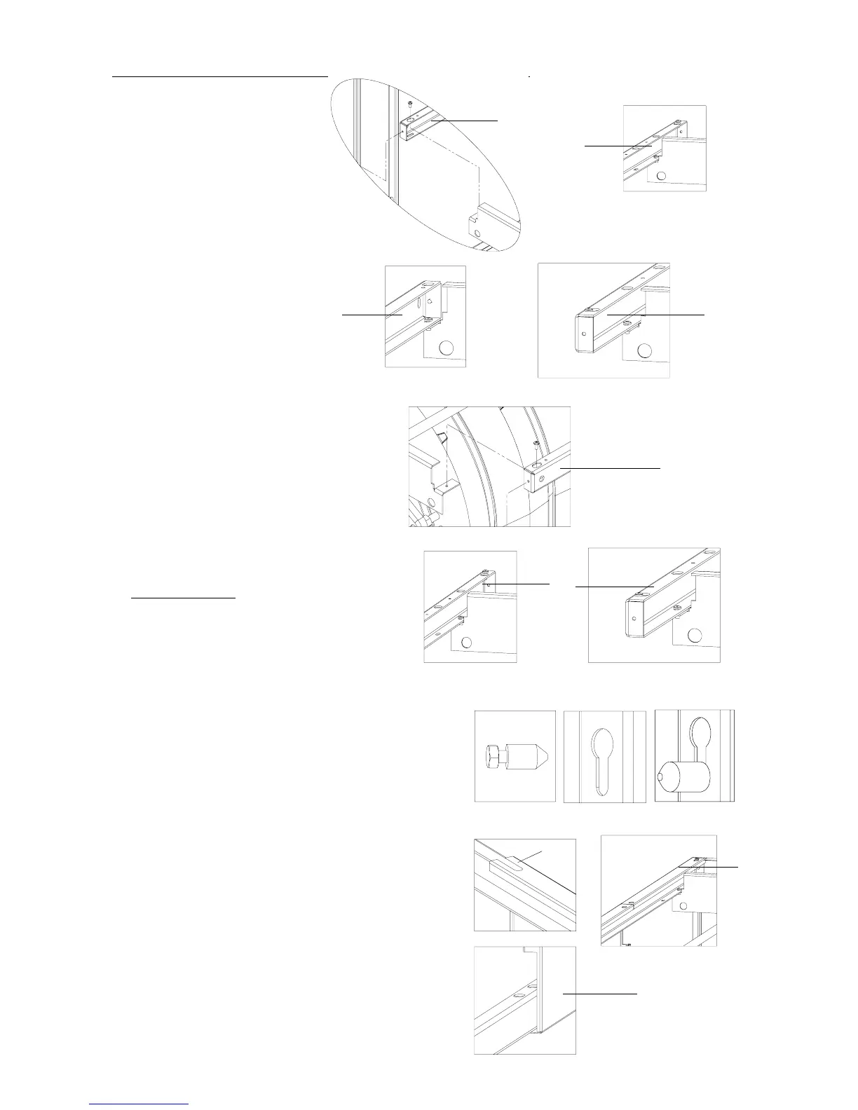
9. Fixing of the left upper guide.
- 2 Parker screws 4.2X10
10. Fixing of the right upper guide.
- 2 Parker screws 4.2X10
10 10
10
11. Placi ng of the set s crew at the bottom of the
2 upper guides.
Screw only 2 times
- 2 Parker screws 4.2X10
12. P lacing of the centering studs on the panels.
12.1 .Screw the M4 scr ew on the cente ring stud
(drawing A)(donotblock).
12.2. Insert the unit (stud external side) in the
oblong hole (drawing B),
Slip the unit in the back of the oblong and
tighten the thrust screw M4 (drawing C).
- from 4 to 12 centeri ng studs Ø8X 16 (M4)
according to model. 4 centering studs for the
Commodore Plus 5 & 6, 8 centering studs for the
Commodore P lus 7, 8, 9 & 1 0, 12 centering studs
for the Commodore Plus 11, 12, 13 & 14.
- from 4 to 12 thrust screws M4X6 according to
model. 4 thrust screws for t he Commodore Plus 5
& 6, 8 thrust screws for the Commodore Plus 7, 8 ,
9 & 10, 1 2 thrust screws for the Commodore Plus
11, 1 2, 13 & 14.
AB C
13. Encase the upp er and lower slide from the right r ear panel
on the right lower and upper guides and make sl ip this
one against the P arker screw 4.2x10 fixed at the end of the
right guide.
(rear panel locatable thanks to the oblong hole on upper
edge detail A).
A
13
13
9
9
rear part
front part
front part
rear part
11