3
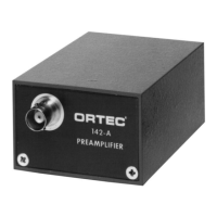
Fig. 2.2. Typical Noise as a Function of
Capacitance Measured with an ORTEC 572
Shaping Amplifier and 0.5-
:
s Time Constant.
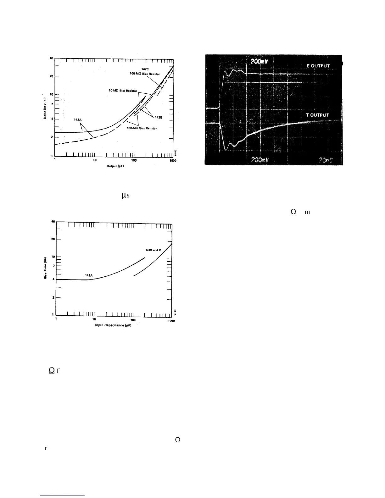
Fig. 2.3. Typical Rise Time Data for 142
Preamplifiers with Rise Time Compensation
Optimized at Each Data Point.
(Values given are for a +0.5-V signal into
93
S
from the E channel.)
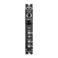
Fig. 2.4. 142A,B, and C Outputs; Detector
Bias Polarity Positive.
2.3. OUTPUTS
E Furnishes the output signals through R
o
= 93
S
for energy measurements; polarity is opposite from
input pulse polarity (Fig. 2.4.).
T Furnishes a differentiated output signal
compatible with typical 50
S
timing system
requirements; polarity is the same as the input pulse
polarity (Fig. 2.4.).
2.4. CONNECTORS
INPUT, TEST, E, AND T BNC (UG-1094/U).
BIAS SHV (AMP 51494-2) or ORTEC type C-38.
POWER CABLE 10-ft captive power cable (ORTEC
121-C1); longer lengths available from ORTEC on
special order.
2.5. ELECTRICAL AND MECHANICAL
POWER REQUIRED Furnished from any ORTEC
main amplifier or from an ORTEC 114 Power
Supply through the built-in captive cable.
142A +24 V, 20 mA; -24 V, 1 0 mA; +1 2 V, 15 mA;
-12 V, 15 mA.
142B +24 V, 40 mA; -24 V. 10 mA; +12 V, 15 mA;
-12 V, 15 mA.
142C +24 V, 40 mA; -24 V, 10 mA; +12 V, 15 mA;
-12 V, 15 mA.
DIMENSIONS 3.8l x6.l x8.89cm(l.5 x2.375 x3.5in.)
plus 10-ft cable.