17
A
R
P
Q
B
M
C
D
R
E
F
N
K
L
G
O
H
I
J2
J1
J3*
S1 S2 S3 S4
1
2
3
4870531-00
To be placed at
the cover of the
power supply.
To be placed
inside the door.
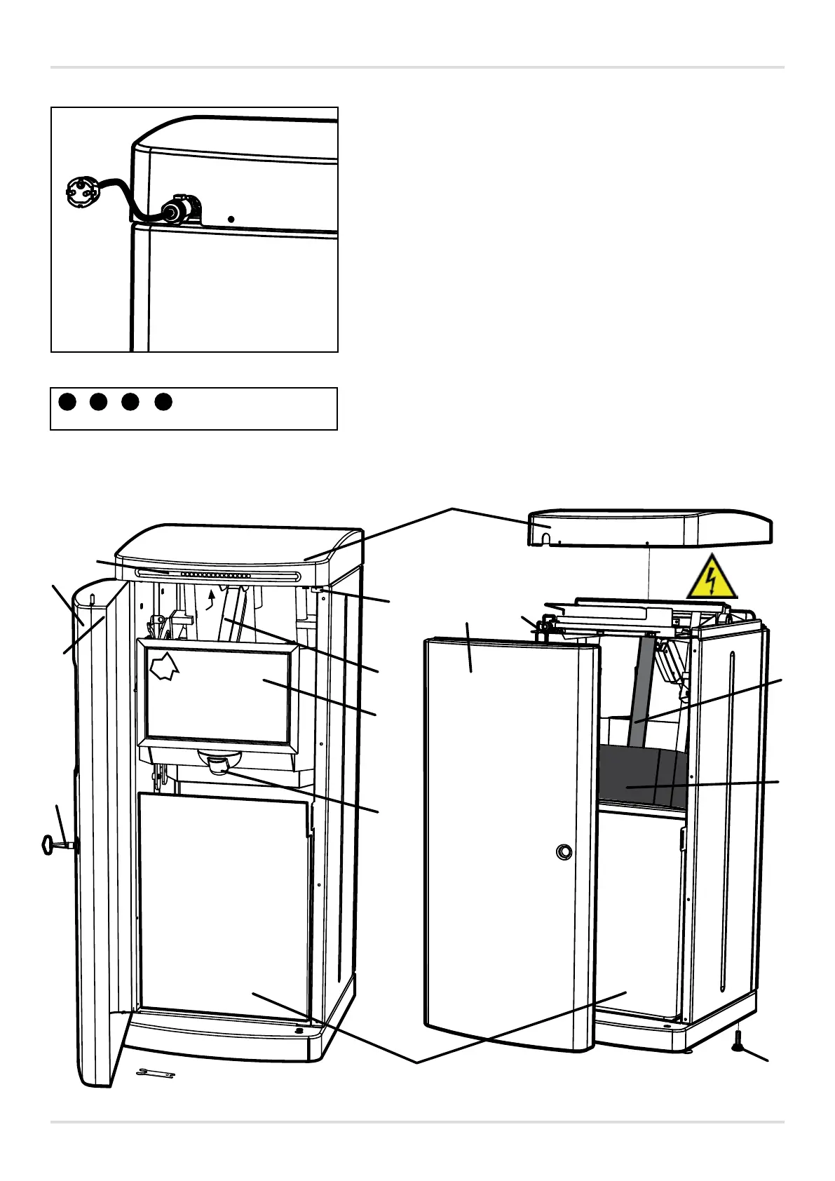
FRONT OF THE MACHINE REAR OF THE MACHINE
MACHINE DESCRIPTION
Parts of the machine
A
Top cover
B
Door
C
Bag holder
D
Feed hatch
E
Press plate
F
Back / Door*
G
Motion sensor (distance sensitivity can be
adjusted by an authorised service technician)
H
Key
I
Adjustable foot
J1
Magnet switch
J2
Magnet
J3*
Magnet (on door version)
K
Large actuator, for the press plate
L
Small actuator, for the feed hatch
M
Display card with LED panel
N
Mains connection (quick-connector, cable and
plug)
O
Spanner for adjusting the adjustable feet
P
Inductive sensor (x 2)
Q
Magnet (for the feed hatch)
R
Buttons (on the display card) for setting the
operating modes
English
5
 Loading...