OSB
Series 2 Oil-Fired Steam Boilers – Boiler Manual
Part Number 550-110-772/0816 11
6 Connect wiring
Electricshockhazard.Cancauseseverepersonal
injury or death if power source, including service
switch on boiler, is not disconnected before installing
or servicing.
Installations must follow these codes:
• NationalElectricalCode,ANSI/NFPA70,latesteditionand
any additional national, state or local codes.
• WiringmustbeN.E.C.Class1.Iforiginalwireassuppliedwith
boiler must be replaced, type 105 °C wire or equivalent must
be used. Supply wiring to boiler and additional control wiring
must be 14 gauge or heavier.
• Provideelectricalgroundatboilerasrequiredbycodes.
Thermostat wiring
• Installthermostatoninsidewallawayfrominuencesofdrafts,
hotorcoldwaterpipes,lightingxtures,television,sunrays
or fireplaces.
• Followinstructionswiththermostat.Ifithasaheatanticipator,
set heat anticipator in thermostat to match power requirements
of equipment connected to it. Boiler wiring diagrams give
setting for standard equipment.
Burner wiring
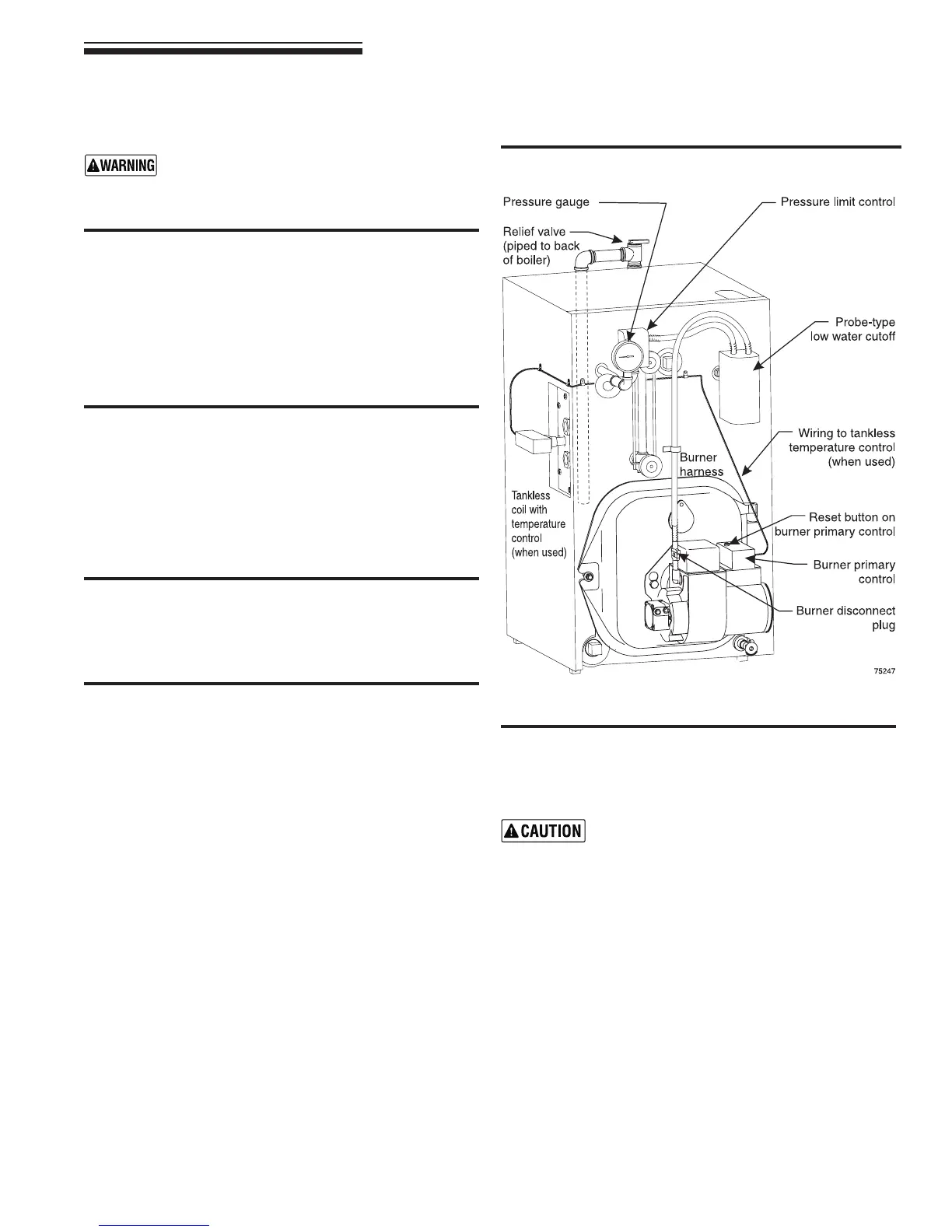
• Burnerharnessincorporatesadisconnectplug,providinga
convenient way to disconnect wiring when burner mounting
door is opened. See Figure 11.
Wiring entrance
• The probe low water cutoff enclosure houses electrical
connections for all boiler components.
• Boilershaveharnessesfurnished.SeeFigure12,page13,
(OSBboilerswithlowwatercutoffs)forfactoryandeldwiring
information.
• Alleld-installedhighvoltagewiringmustbesheathedinmetal
conduit.
• ConnectincominglinevoltagewiresasshowninFigure12,
page 13. Field-install equipment ground wire to green wire
with wire nut.
• Somelocalcodesmayrequireanemergencyshut-offswitch
installed at a location away from boiler. Follow local codes.
Figure 11 Electrical components and harnesses
High Temperature Limit
Installation requirements.
Do not tamper with the unit or controls.
• If installation is to comply with ASME, UL 726 or Canadian
requirements, an additional high temperature limit is needed.
Consult local inspector. Install control in supply piping be-
tween boiler and isolation valve. Set control to a minimum
of 20°F above set point of combination control. Maximum
allowable set point is 220°F. Wire control as shown on wiring
diagram.