OSB
Series 2 Oil-Fired Steam Boilers – Boiler Manual
Part Number 550-110-772/0816 7
General
If installation is to comply with special codes, additional limit
controlsmayberequired.Ifinstallingaoat-typelowwatercutoff,
use only those devices that can be connected to the boiler gauge
glass tappings. Refer to the wiring diagrams on page 13 for correct
wiring location of additional limit controls.
Relief valve
Installboilerreliefvalveinthe¾”tappinginthebackoftheboiler,
usingthe¾”nippleandelbowsuppliedinthebagwithreliefvalve.
Follow the steps below to avoid potential severe
personal injury, death or substantial property damage.
• When installing the relief valve,ensure that all
connections, including the valve inlet, are clean and
free from any foreign matter.
• Mountthereliefvalveonlyintheverticalposition,
directly connected to the tapping designated in the
manual on top of the boiler.
• Usepipecompoundsparingly,ortape,onexternal
threads only.
• Donotuseapipewrench!Usepropertypeandsize
wrench on wrench pads only.
During operation, this valve may discharge large
amounts of steam and/or hot water. Therefore, to
reduce the potential for bodily injury and property
damage,adischargelineMUSTbeinstalledthat:
• Is connected from the outlet to a safepoint of
discharge with no intervening valve.
• Allowscompletedrainageofboththevalveandthe
discharge line.
• Isindependentlysupportedandsecurelyanchored
so as to avoid applied stress as possible.
• Terminatesfreelytoatmospherewhereanydischarge
willbeclearlyvisibleandisatnoriskoffreezing.
• Is,overitsentirelength,ofapipesizeequaltoor
greater than that of the valve outlet.
Use only schedule 40 metal pipe for discharge.
(Do not use schedule 80, extra strong or double
strongpipeorconnections.)DONOTCAP,PLUG
OROTHERWISEOBSTRUCTDISCHARGEPIPE
OUTLET!Ifdischargeispipedupward,acondensate
drain must be provided in the elbow below the vertical
pipe to prevent condensate from returning into the
valve. Failure to comply with these instructions will
cause a dangerous spray of hot water and steam
that would cause severe personal injury or death.
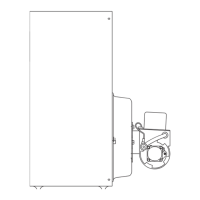
Connecting to counterflow piping
ApplytherecommendedpipinginFigures4through7onlywhen
connecting to a parallel-flow system. When connecting to a
counterflow system, the boiler steam supply must connect into the
top of the counterflow system header, as shown in Figure 3, below.
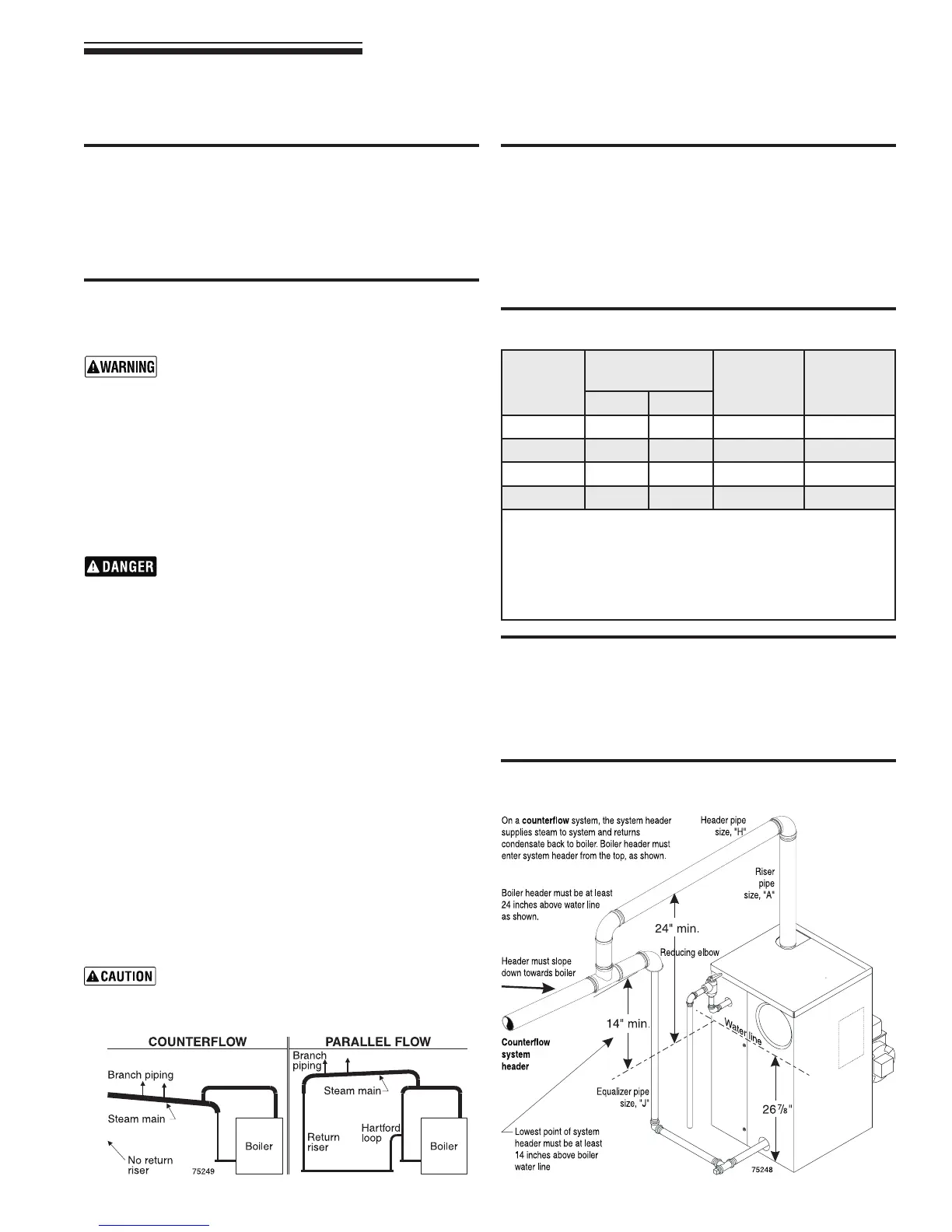
Figure 3 Connection to counterow steam piping only
(for parallel ow systems, see page 8)
The piping in Figure 3 applies only to the special
case of counterflow steam systems. Refer to page
8 for parallel flow steam systems. See below.
4 Connect steam piping
Table 4 Recommended pipe sizing
Near-boiler piping
SeeFigures4and5,page8,forrecommendedpipingofboilersizes
OSB-3,-4and-5.SeeFigures6and7,page8,forrecommended
pipingofOSB-6boilers.Thesepipingrecommendationsapplyonly
to connections to parallel-flow one-pipe and two-pipe systems.
For counterflow systems, connect boiler supply and return to
counterflow system header as shown in Figure 3, below. Table 4,
below,givesrecommendedpipesizes.
Boiler
model
number
Riser
pipe size
(Note 1)
Header
pipe size
“H”
(Note 2)
Equalize
pipe size
“J”
A B
OSB-3 2-1/2” --- 2-1/2” 1-1/2”
OSB-4 2-1/2” --- 2-1/2” 1-1/2”
OSB-5 2-1/2” --- 3” 1-1/2”
OSB-6 2-1/2” 2-1/2” 4” 1-1/2”
Notes:
1. Based on ASHRAE Fundamentals Handbook recommendations,
allowing ½ oz. pressure drop at 0 psig.
2. Based on ASHRAE Fundamentals Handbook recommendations,
allowing 2 oz. pressure drop per 100 feet of pipe at 3.5 psig.
Maintain minimum 24” height from waterline to bottom of header.
Note Figure 3, showing the special connection required to a
counterow system.