Do you have a question about the OSC RMX 850 and is the answer not in the manual?
List of service bulletins issued for QSC RMX Series amplifiers.
Essential tools and equipment needed for servicing RMX amplifiers.
Guidance on working with SMT components in RMX amplifiers.
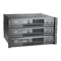
Description of the RMX Series amplifiers, including models and features.
Detailed technical descriptions and theory of operation for RMX amplifiers.
Pin configuration for the NE5532AN dual operational amplifier.
Pinout details for the LM13600 dual operational transconductance amplifier.
Pin configuration for the LM311 voltage comparator.
Pinout diagram for the 4N29 opto-isolator.
Diagnosing and resolving issues related to excessive current draw.
Resolving problems with protection circuits, muting, and delays.
Addressing issues when the amplifier passes signal but malfunctions.
Identifying and fixing instability, noise, or oscillations.
Resolving power supply and rail voltage balancing issues.
Procedure for setting the bias on RMX amplifier channels.
Steps to calibrate positive and negative current limiting.
Instructions for disassembling and re-assembling RMX amplifiers.
List of replacement parts for the RMX 850 amplifier.
List of replacement parts for the RMX 1450 amplifier.
List of replacement parts for the RMX 2450 amplifier.
Diagram showing RMX amplifier assembly and disassembly steps.
Second diagram for RMX amplifier assembly and disassembly.
Schematic diagram for Channel 1 of the RMX 850 amplifier.
Schematic diagram for Channel 2 of the RMX 850 amplifier.
Schematic diagram of the RMX 850 amplifier's power supply.
Schematic diagram for Channel 1 of the RMX 1450 amplifier.
Schematic diagram for Channel 2 of the RMX 1450 amplifier.
Schematic diagram of the RMX 1450 amplifier's power supply.
| Channels | 2 |
|---|---|
| Frequency Response | 20Hz-20kHz |
| Input Sensitivity | 0.775V |
| Input Impedance | 20kΩ Balanced / 10kΩ Unbalanced |
| Protection | DC, thermal, short circuit, overload |