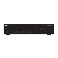
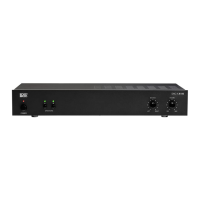
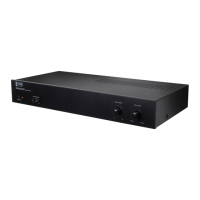
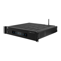
FRONT/REAR PANELFRONT/REAR PANEL
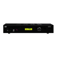
CONTROL12MAX8
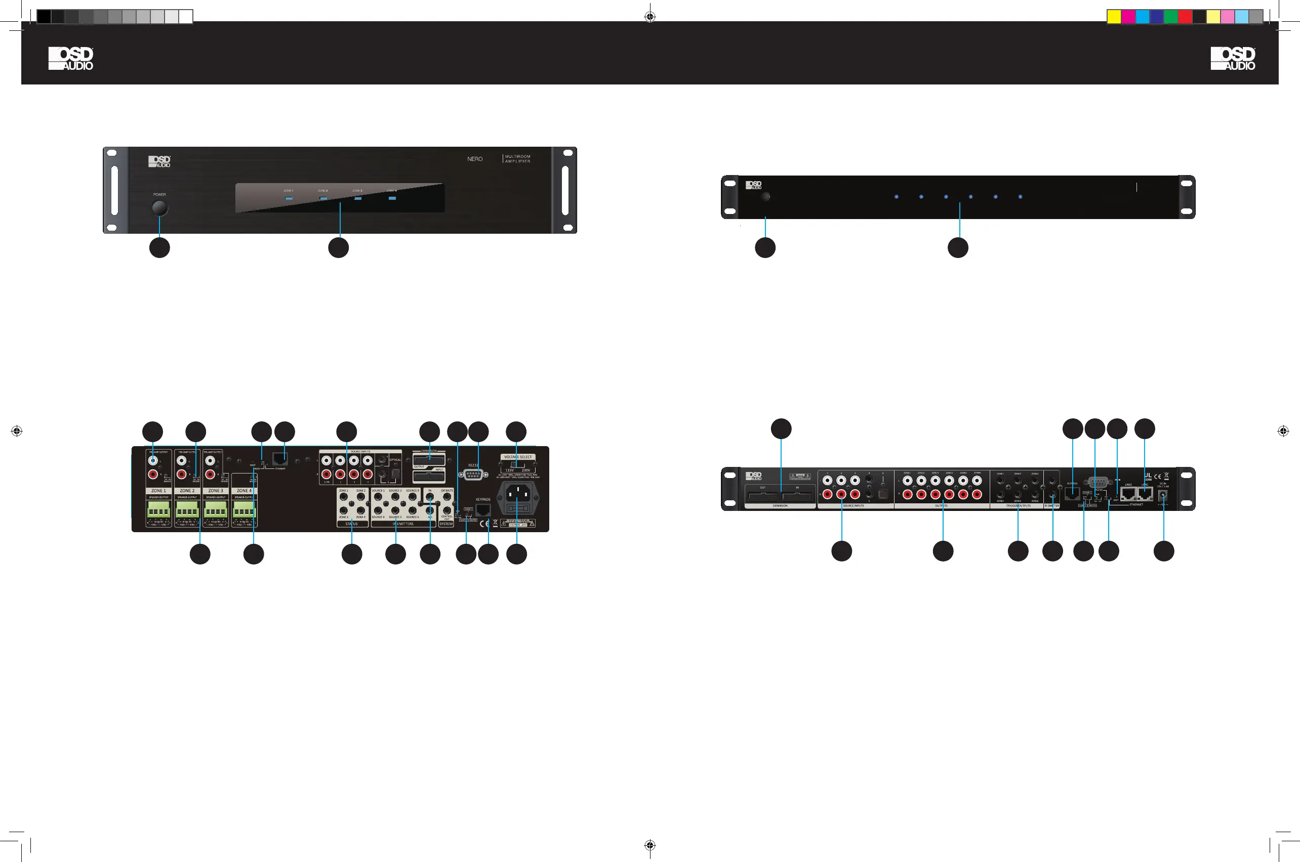
1. Power ON/OFF/ STANDBY
Depress the power button to turn on the system. Press it
again to release the latch and power the unit off.
Note: Even if the power is on, each zone will remain in
Standby mode until the zone is activated by command
from either OSD Control App, keypad, or RS232.
2. Standby/Zone ON LED
These 6 LEDs illuminate to indicate the
status of each zone.
Blue: In Standby mode.
White: In Activate mode.
Blue/White: In Mute mode.
MAX8
UL
62368
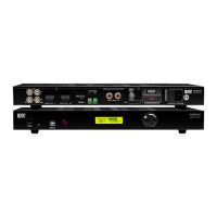
1. Power ON/OFF/ STANDBY
Depress the power button to turn on the system. Press it
again to release the latch and power the unit off.
Note: Even if the power is on, each zone will remain in
Standby mode until the zone is activated by command
from either OSD Control App, keypad, or RS232.
2. Standby/Zone ON LED
These 4 LEDs illuminate to indicate the
status of each zone.
Blue: In Standby mode.
White: In Activate mode.
Blue/White: In Mute mode.
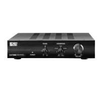
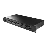
1. PRE-AMP OUTPUT
Stereo Line level output on each zone. Connect to the
input of ampliers or powered speakers.
2. SOURCE INPUTS Source1-3: RCA Stereo Input
Source4-5: 3.5mm Stereo Input Source6: OPTICAL
Digital Input
3. TRIGGER OUTPUT When the zone is activated, the
corresponding jack will output 12VDC to trigger another
device.
4. IR EMITTERS
5. KEYPAD RJ-45 jack Connects to the keypad hub for
up to 6 keypads.
6. MASTER/SLAVE SWITCH Set the unit ID when
connecting multi-Controller systems
7. AGC Automatic Gain Control auto balances input level
differences.
8. ETHERNET/RS232 SWITCH
ETHERNET: When the amplier connects to Ethernet.
RS232: When the amplier control by PC or Control
Device via RS-232 port.
9. ETHERNET PORTS Dual LAN ports, one connects to
the LAN port of local router. Another connects to network
TV or another device which requires Ethernet.
10. RESET The RESET button is used to reset the
ETHERNET back to factory default settings.
11. EXPANSION IN/OUT PORT
Expandable to 18 zones with 3 x Multi-zone Controller
systems.
12. DC INPUT Connect the supplied DC adapter to the
DC IN jack, and then plug it into a standard household
outlet
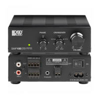
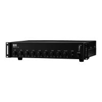
1. PRE-AMP OUTPUT x 3
Stereo Line level output for each zone. Connect to the
input of ampliers or powered speakers.
2. Bridge mode selector: See Page 11 for more details
on using the Bridge mode.
3. Speaker Outputs
4. Ethernet port
5. Zone Status: Used to control external Zone Devices
6. Source Inputs (Input 1/PA)
7. IR Outputs to control Sources
8. A) PA Trigger IN (Source 1) B) MUTE In/Control
Out: This input can temporarily mute the system by
connecting this unit to a relay closure switch on home
automation system or phone system etc. When switch is
on, it will short-circuit the input and mute the unit.
9. Expansion IN/OUT Port: Connects up to 3 units total
10. RS232 Port
11. Voltage Selector (115V in US)
12. AC Input
13. Keypad Hub Input
14. AGC ( Automatic Gain Control ): brings low input
levels up to a preset-level
15. Unit ID Switch
16. RS232 or Ethernet control switch
17. RESET The RESET button is used to reset the
ETHERNET back to factory default settings.
18. ETHERNET/RS232 SWITCH: ETHERNET - When
connecting the device via Ethernet to your Network.
RS232 - When the device is controlled by PC or 3rd
Party Control Device via RS-232 port.
11
11
1 2 416 6 9
7 10
10
5
14
9
11
2
3 17
1
5
3
7
8
13
6
NERO-CONTROL12
NERO-CONTROL12
2022-08-03
POWER
ZONE 1 ZONE 2 ZONE 3 ZONE 4 ZONE 5 ZONE 6
NERO CONTROL12
MULTI-ZONE
CONTROLLER
15
4
8
12
12
22
NERO-CONTROL12
NERO-CONTROL12
2022-08-03
POWER
ZONE 1 ZONE 2 ZONE 3 ZONE 4 ZONE 5 ZONE 6
NERO CONTROL12
MULTI-ZONE
CONTROLLER
NERO MAX-CNTRL man.indd 6-7 11/14/22 11:37 AM
 Loading...