INTRODUCTION FRONT/REAR PANEL
MAX12
The NERO MAX12, MAX8 and CONTROL12 are functional, easy to install, highly compatible, expandable, and user-
friendly audio distribution systems. They feature 6 Analog Source Inputs, the MAX12 and MAX8 providing up to 80W
@4-ohm from a Class D amplier for 6 or 4 zones - expandable to 18 zones, which can be controlled by the either
the OSD Control App (Free App that Duplicates the Keypads), Optional Keypads with IR Remote Control or RS-232.
The CONTROL12 offers the same 6 sources with pre-amp outputs only. Allowing for integration with alternative,
more powerful, amps such as the MX Series.
FEATURES:
• 6x6 or 6x4 Audio Matrix Switch and 6 Source Inputs.
• MAX12 and MAX8 have 6 or 4 Stereo, Bridgeable, amplied speaker outputs.
• Expandable to 2 or 3 units, giving 8/10/12/16/ and 18 stereo zones of distributed Audio.
• Free iOS & Android App (2.4GHz wireless networks only) duplicates the Control Panels for each Zone/Room.
Optional Control Pads/IR Remote are available as well.
• High Efciency Class D Amplier (MAX12 & MAX 8); 80 watts (4-ohms) and 40 watts (8-ohms) Each Zone
can drive a single 4-ohm pair of speakers or two pair of 8-ohm speakers, Stereo or Bridged Mono Output for combining ones for
100 Watts at 8 ohms (single 8-Ohm speaker per channel only)
• 3 Stereo line-level Pre-AMP L&R RCA Outputs (Zones 1-3) – MAX12 & MAX8 only
• 6 Stereo line-level Pre-AMP L&R RCA Outputs (Zones 1-6) – CONTROL12 only
• 4 Stereo line-level L&R RCA Analog Source Inputs, 1 Mini 3.5 mm Stereo Analog input, 1 auto-selecting Optical or
Mini 3.5 Analog
• Optional keypads have a built-in IR receiver & IR remote controller for Source select/Volume/Treble/Bass.
• RS232 for transferring and receiving the serial data for control systems.
• 6 Individual Zone Status (3.5mm): Used to control external Zone Devices (12V triggers)
• 6 IR Emitter 3.5mm Mono RCA outputs + 1 IR Emitter/Blaster 3.5mm Mono Jack (MAX12 and MAX8 only),
CONTROL12 - 2 IR Emitter 3.5mm Mono RCA outputs + 1 IR Emitter/Blaster 3.5mm Mono Jack
• Front panel LEDs for 6/4 zones indicating Power On, Standby and Mute.
• 1 PA Input jack to set all zones to Source 1 (12Vdc Trigger)
• External Mute In/Control Out (3.5mm Mono Jack RCA connections/12Vdc)
• AGC (Automatic Gain Control): brings low input levels up to a present-level
• Unit ID Selector Switch: Master/Slave 1/Slave 2(Expandable settings)
• Multi Voltage Selector 115V or 230V, AC Input connection with Fuse Receptacle (CE Certied)
SPECS:
Power: (MAX12 and MAX8 only):
8 Ohm - 40W x 2 per zone 4 Ohm - 80W x 2 per zone
Bridgeable: 8 Ohm Only - 80W
S/N: MAX12 and MAX8 - >85dB A WTD
S/N: CONTROL12 -110dB
THD: MAX12 and MAX8 - <0.1%
THD: CONTROL12 – 0.05% (0.5dB)
Freq Response: 20Hz-20KHz
Input Impedance: >47 K Ohm
Output Impedance (line level) 100 Ohms
Input Sensitivity: 250mv
Protection: Overload, Short Circuit, Temperature
System Voltage: DC +12V
External Mute and TRIGGER OUT Voltage: DC +12V
Network Connector: RJ45, Standard 10/100Mb
Power Supply: AC 115V/60Hz - 230V/50Hz (CONTROL12 DC 15V/1.6A)
Output Connection: Terminal Block
Dimensions: 16.9” W x 3.5” H x 16.4” D (MAX12 and MAX8)
16.9” W x 1.75” H x 16.4” D (Control12)
Weight: MAX12 25lbs, MAX8 19lbs, Control12 4.5lbs
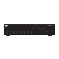
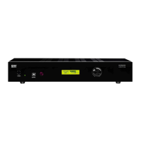
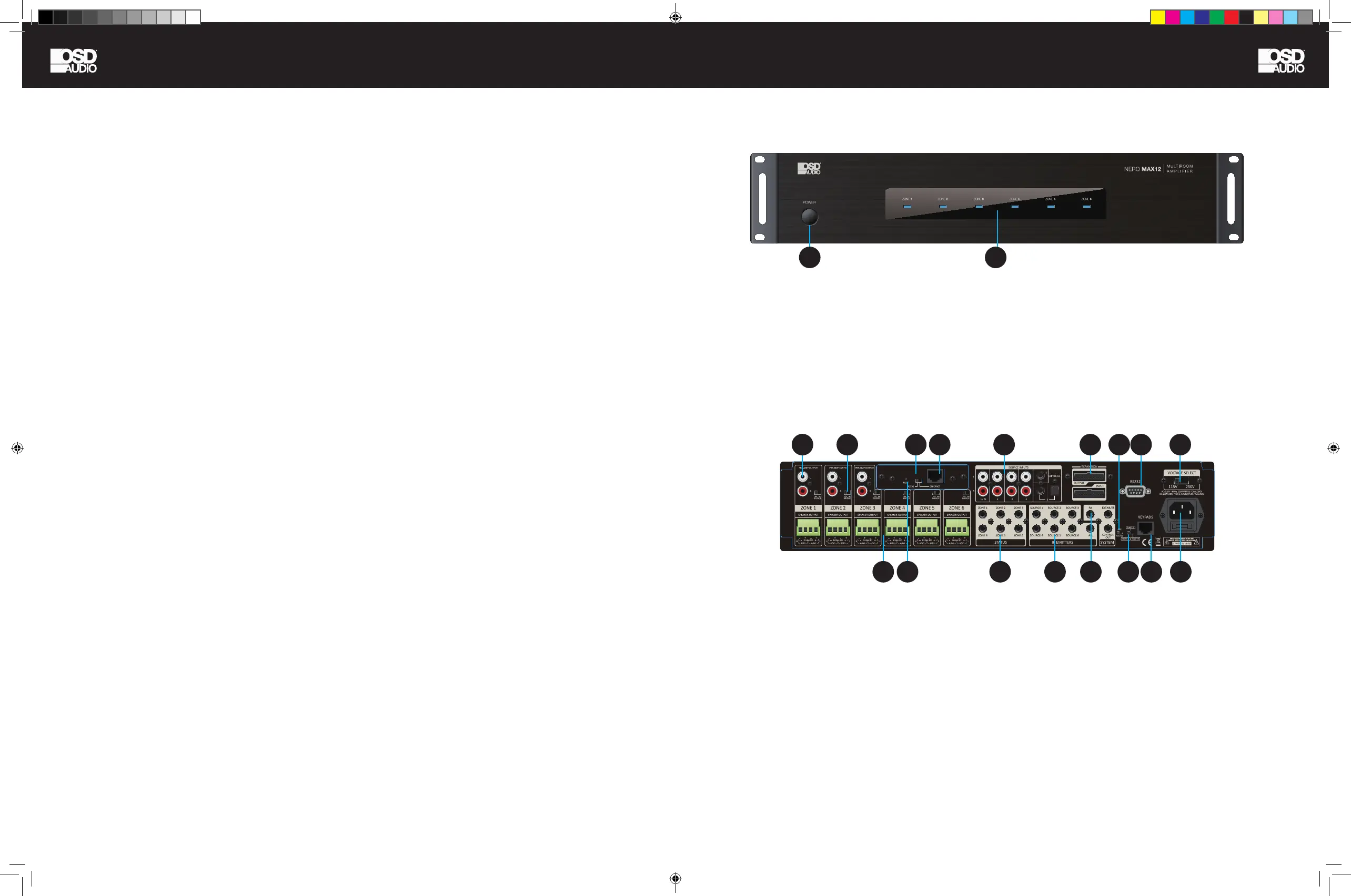
1. Power ON/OFF/ STANDBY
Depress the power button to turn on the system. Press it
again to release the latch and power the unit off.
Note: Even if the power is on, each zone will remain in
Standby mode until the zone is activated by command
from either OSD Control App, keypad, or RS232.
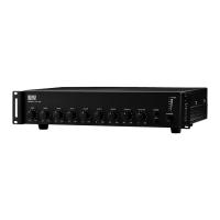
2. Standby/Zone ON LED
These 6 LEDs illuminate to indicate the
status of each zone.
Blue: In Standby mode.
White: In Activate mode.
Blue/White: In Mute mode.
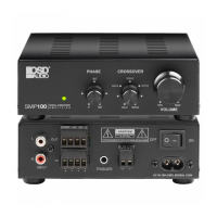
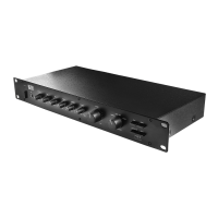
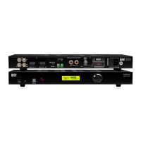
1. PRE-AMP OUTPUT x 3
Stereo Line level output for each zone. Connect to the
inputs of ampliers or powered speakers.
2. Bridge mode selector : See Page 11 for more details
on using the Bridge mode.
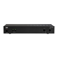
3. Speaker Outputs
4. Ethernet Port
5. Zone Status: Used to control external Zone Devices
6. Source Inputs (Input 1/PA)
7. IR Outputs to control Sources
8. A) PA Trigger IN (Source 1) B) MUTE In/Control
Out: This input can temporarily mute the system by
connecting this unit to a relay closure switch on home
automation system or phone system etc. When switch is
on, it will short-circuit the input and mute the unit.
9. Expansion IN/OUT Port: Connects up to 3 units total
10. RS232 Port
11. Voltage Selector (115V in US)
12. AC Input
13. Keypad Hub Input
14. AGC ( Automatic Gain Control ): brings low input
levels up to a preset-level
15. Unit ID Switch
16. RS232 or Ethernet control switch
17. RESET: The RESET button is used to reset the
ETHERNET back to factory default settings.
18. ETHERNET/RS232 SWITCH: ETHERNET - When
connecting the device via Ethernet to your Network.
RS232 - When the device is controlled by PC or 3rd
Party Control Device via RS-232 port.
CONTENTS:
• NERO MAX12 Amp or MAX8 or Control12
• Expansion Ribbon Cable
• Rack Ears
• Speaker Terminal Blocks (Pre-Installed on Amp)
• AC Power Cable
• Product Manual
N E R O -M A X 1 2
2022-07-20
UL
62368
N E R O -M A X 1 2
2022-07-20
UL
62368
1
1 2 416 6 9 1014 11
3 17 5 7 13158 12
2
NERO MAX-CNTRL man.indd 4-5 11/14/22 11:37 AM
 Loading...