Do you have a question about the OSTBERG HERU S Series and is the answer not in the manual?
A warning states a risk of personal injury.
A caution states a risk of damage to equipment.
All electrical installations must be performed by a qualified electrician.
Details about the product label and its components.
The HERU unit must be stored in a protected and dry space before installation.
Inspect the unit carefully upon delivery to check for any damage.
Details on mounting principles, placement, and required distances for HERU units.
Instructions for charging and setting up the wireless IQC display.
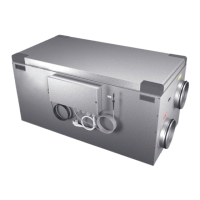
Comprehensive steps for installing the HERU S unit, including dismounting and reassembly.
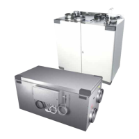
Comprehensive steps for installing the HERU T unit, including dismounting, reassembly, and cooker hood connection.
Instructions for connecting the unit to power and external control equipment via Modbus.
Steps to power up and initiate the HERU unit.
Guide to setting up the unit's parameters via the service menu.
Instructions to configure airflow direction for HERU S.
Steps to configure Modbus communication settings.
Details for internal, supply, and room temperature sensors.
Information on BMS, LAN, and Modbus connections.
Details for heating coil, fan, and damper control outputs.
Information about the main 230V power supply and PE connections.
| Brand | OSTBERG |
|---|---|
| Model | HERU S Series |
| Category | Test Equipment |
| Language | English |