30
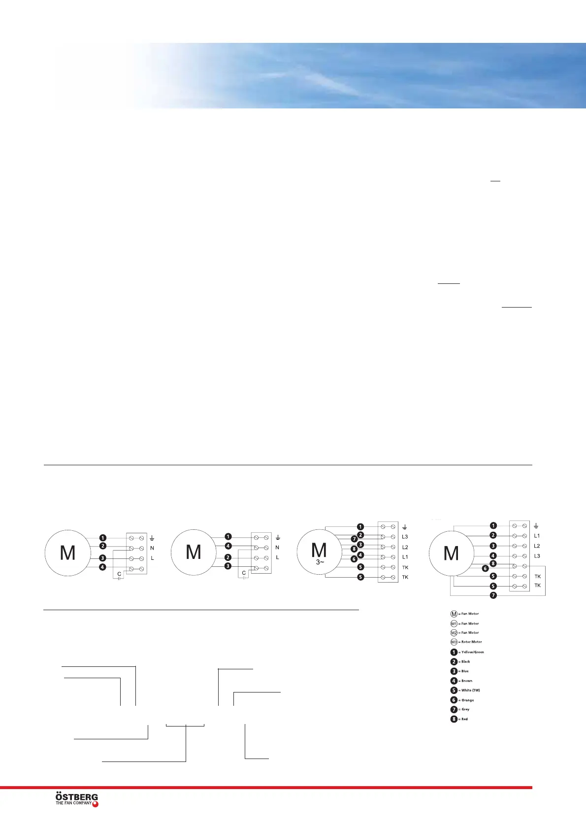
Wiring diagrams
Key to model types
GENERAL FAN FACTS
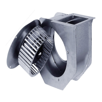
RFE 250 B KR
Fan
Radial
E = Single phase
T = 3-phase
Duct dimension Ø
A, B, C, D, E, F, G, H, L,
M, P, R or S = Capacity
K = with junction box
U = without junction box
R = with connection pipe
U = without connection pipe
4040004
3-phase Y 400 V
4040001
Single phase
4040002
Single phase
4040003
3-phase
DESCRIPTION
• The fan is used for transportation of “clean”
air, meaning not intended for fire-dangerous
substances, explosives, grinding dust, soot,
etc.
• The fan is equipped with an asynchronous
external rotor induction motor with mainte-
nance-free sealed ball-bearings.
• The capacitor has finite lifetime and should
be exchanged after 45.000 hours of opera-
tion (about 5 years) to secure maximum
function. Defective capacitor can cause
damage.
• To achieve maximum life time for installa-
tions in damp or cold environments, the fan
should be operating continuously.
• The fan can be installed outside or in other
damp environments. Make sure that the fan-
house is equipped with drainage.
• The fan is used at the voltages/frequencies
according to the product label.
• The fan can be installed in any position.
INSTALLATION
• The fan must be installed according to the air
direction label on the fan.
• The fan must be connected to duct or equip-
ped with a safety grille.
• The fan should be installed in a safe way and
make sure that no foreign objects are left be-
hind.
• The fan should be installed in a way that
makes service and maintenance easy.
• The fan should be installed in a way that
vibrations can not be transfused to duct or
building.
• To regulate the speed, a transformer, a triac
or a frequency converter can be connected.
• A wiring diagram is applied on the inside of
the junction box or separately enclosed.
• The fan must be installed and connected
electrically in the correct way grounded.
• Always use the internal thermo-contact, see
wiring diagram.
• Electrical installations must be made by an
authorized electrician.
• Electrical installations must be connected to
a locally situated tension free switcher or by
a lockable head switcher.
OPERATION
When starting, make sure that:
• the current does not exceed more than +5 %
of what is stated on the label.
• the connecting voltage is in between +6% to
–10% of the rated voltage.
• no noise appears when starting the fan.
• the rotation direction at 3-phase motors are
according to the label.
HOW TO HANDLE
• The fan must be transported in its packing
until installation. This prevents transport
damages, scratches and the fan from getting
dirty.
• Attention, look out for sharp edges and cor-
ners.
MAINTENANCE
• Before service, maintenance or repair begins,
the fan must be tension free and the impeller
must have stopped.
• Consider the weight of the fan when remo-
ving or opening larger fans to avoid jamming
and contusions.
• The fan must be cleaned when needed, at
least once per year to maintain the capacity
and to avoid unbalance which may cause
unnecessary damages on the bearings.
• The fan bearings are maintenance-free and
should be renewed only when necessary.
• When cleaning the fan, high-pressure clea-
ning or strong dissolvent must not
be used.
• Cleaning should be done without dislodging
or damaging the impeller.
• Make sure that there is no noise from the
fan.
FAULT DETECTION
1. Make sure that there is tension to the fan.
2. Cut the tension and verify that the impeller
is not blocked.
3. Check the thermo-contact/motor protector.
If it is disconnected the cause of overheating
must be taken care of, not to be repeated. To
restore the manual
thermo-protector the
tension will be cut for a couple of minutes.
Larger motors than 1,6 A may have manual
resetting on the motor. If it has automatic
thermo-protector the resetting will be done
automatically when the motor is cold.
4. Make sure that the capacitor is connected,
(single phase only) according to the wiring
diagram.
5. If the fan still does not work, the first thing
to do is to renew the capacitor.
6. If nothing of this works, contact your fan
supplier.
7. If the fan is returned to the supplier, it must
be cleaned, the motor cable undamaged and
a detailed nonconformity report enclosed.
WARRANTY
The warranty is only valid under condition that
the fan is used according to this “Directions for
use”.
 Loading...