Radian-Class Inverter Data Stream
12 900-0137-01-00 Rev A
EXAMPLE
:
A grid-interactive inverter has a
SellRE
setting of 51.2 Vdc and 10 amps
(1200 watts) of AC output load on L1. DC sources contribute 480 watts to
the battery. The inverter maintains the battery at 51.2 Vdc by converting
the excess 480 watts of DC power to AC. The inverter mode displays
Support
with the
Inverter Current
meter showing 4 amps (480 watts) of
production. The
Buy Current
would show 6 amps (720 watts), for 600
watts of total AC load current. If the AC load was removed, the inverter
would have
Sell Enabled
as the mode and show 4 amps of
Sell Current
.
Error Codes
: This is an ASCII expression of an 8-bit binary string, displayed in values ranging from 000 to 255.
Each bit represents a different error as shown in Table 10. If more than one error occurs, the values are additive.
For example, an overtemp error and backfeed error would return an ASCII value of 132 (a binary value of
1000100).
AC Mode
: This represents the status of the AC input. The range is 00 to
99, but only three states are in use.
No AC
means that no AC source has
been detected by the inverter.
AC Drop
means that AC is present but the
inverter is not allowed to accept it.
AC Use
means AC is present and
valid, and the inverter will utilize it.
Battery Voltage
: The DC voltage as measured at the inverter’s battery
terminals. The range is 000 to 999, incorporating one decimal place. For
example, a 24.8 Vdc battery voltage will be sent as ‘248’. The resolution
of battery voltage is 0.1 Vdc for 12-volt systems, 0.2 Vdc for 24-volt
systems, and 0.4 Vdc for 48-volt systems.
Misc Byte
: This is an ASCII expression of an 8-bit binary string, displayed
in values ranging from 000 to 255. Only certain bits are in use at this
time. Each bit represents a different condition. Bit 7 indicates the priority
of the inverter’s two AC inputs. Bit 8 indicates the Radian inverter’s
nominal output voltage.
Warning Codes
: This is an ASCII expression of an 8-bit binary string,
displayed in values ranging from 000 to 255. Each bit represents a
different warning as shown in Table 13. If more than one warning occurs,
the values are additive. For example, a low AC input voltage and low AC
input frequency would return an ASCII value of 010 (a binary value of
00001010).
Checksum
: This is a simple additive checksum of the decimal values of
the data stream. Range is 000 to 999.
EXAMPLE:
00,6,00,00,00,00,119,000,119,00,00,00,00,121,000,121,04,000,02,554,128,000,067
0+0+6+0+0+0+0+0+0+0+0+1+1+9+0+0+0+1+1+9+0+0+0+0+0+0+0+0+1+2+1+0+0+0+1+2+1+0+4+0+0
+0+0+2+5+5+4+1+2+8+0+0+0=067
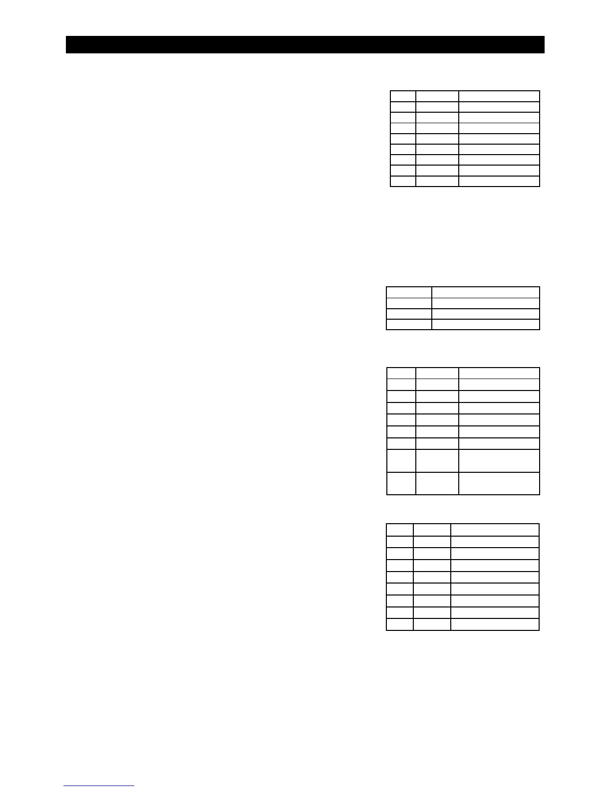
Table 10 Radian Error Codes
Bit Value Error
1 1 Low Vac Output
2 2 Stacking Error
3 4 Over Temp.
4 8 Low Battery
5 16 Phase Loss
6 32 High Battery
7 64 Shorted Output
8 128 Backfeed
Table 11 Radian AC Modes
Value Mode
00 No AC
01 AC Drop
02 AC Use
Table 12 Radian Misc
Bit Value Error
1 1
Reserved by inverter
2 2
Reserved by inverter
3 4
Reserved by inverter
4 8
60 Hz Output
5 16
AUX output ON
6 32
Relay output ON
7 64
1 = AC 1 selected
0 = AC 2 selected
8 128
1 = 230 Vac inverter
0 = 120 Vac inverter
Table 13 Radian Warning Codes
Bit Value Warning
1 1 AC Input Freq High
2 2 AC Input Freq Low
3 4 Input Vac High
4 8 Input Vac Low
5 16 Buy Amps > Input size
6 32 Temp Sensor Failed
7 64 Comm Error
8 128 Fan Failure