USER’S MANUAL FOR MAINTENANCE, CONTROL & INSTALLATION OF THE
“OUTLINE GTO ARRAY” – Translation of the original instructions
Page 22/31
5.4 Connection tests
ATTENTION! If the array has been correctly installed, the following conditions
must be satisfied:
1. all the bracing pins (on all the elements of the array and on both sides) must
be fitted;
2. all the pins with locking button (on all the elements of the array, on the front
and rear connections and on both sides) must be fitted, except those for
setting the angle of the bottom element of the array, as no further element is
fitted to it;
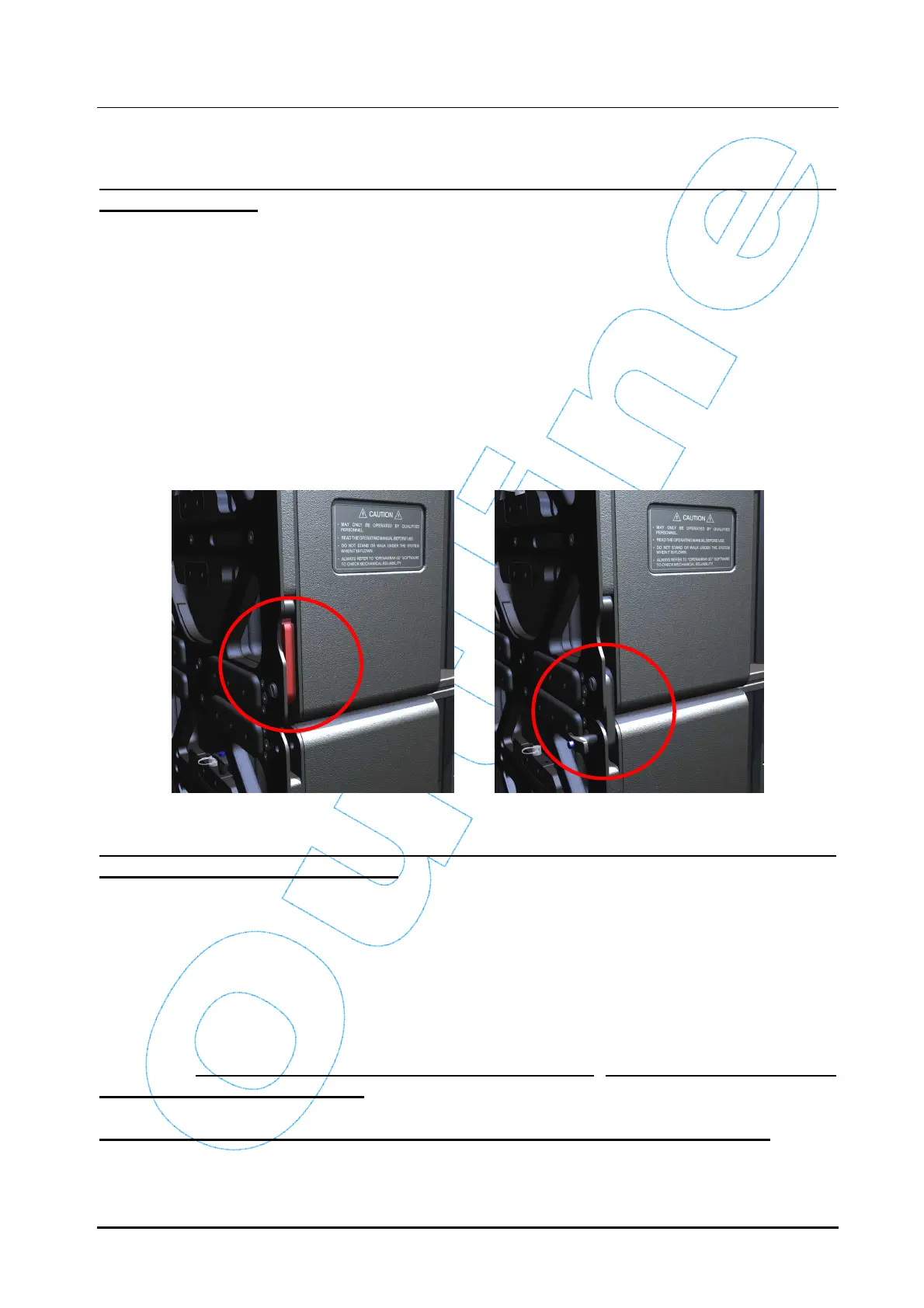
3. As well as being held in place with the pin with locking button, as described
in the previous point, the BLACK parts of all the rear connection brackets
must be seen. If the RED parts can be seen, this means the rear brackets
have not been positioned correctly and the system must be immediately re-
installed correctly.
ATTENTION! Carry out checks as the array raised, in order to avoid any risk of
incorrect installation or breakage.
5.5 Connecting the frame to the hoists
The frame must be connected to at least two hoists, one hooked on to the front shackle
and the other hooked on to the rear one. Alternatively, the four side shackles can be
used.
Lifting work is a very important delicate procedure. As already stated, lifting must be
carried out very slowly and without sudden movements, checking in particular the
load’s stability and oscillation.
It is absolutely forbidden to stand under the load or in its immediate vicinity.
At the end of raising procedure, once the necessary height has been reached, fix the
system to the support structure, using an appropriate security cable.


 To Next Page