USER’S MANUAL FOR MAINTENANCE, CONTROL & INSTALLATION OF THE
“OUTLINE GTO ARRAY” – Translation of the original instructions
Page 8/31
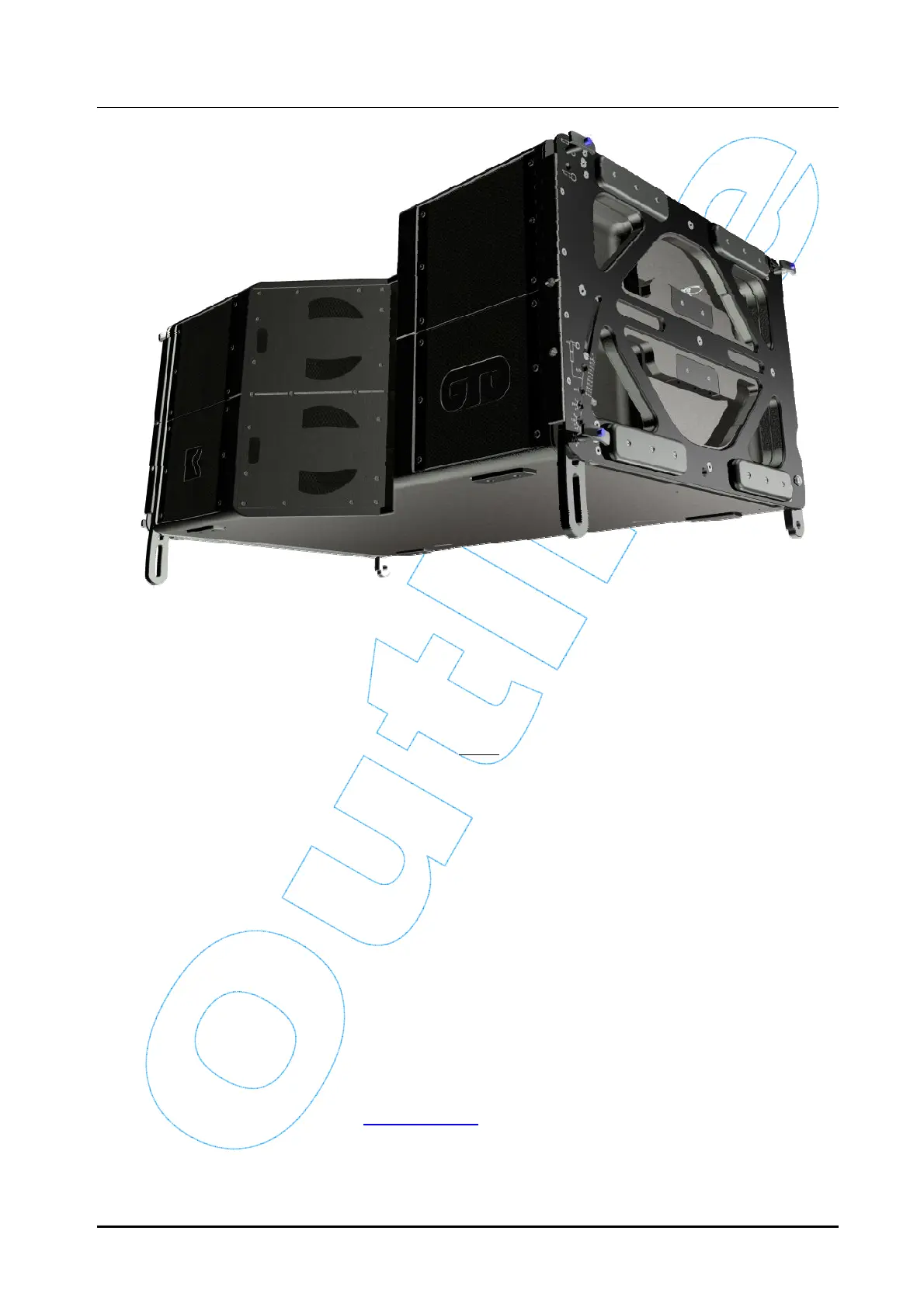
Figure 5 – GTO: Integrated hardware
The mechanical structure consists in two pairs of metal plates (one on either side) and a
series of “fold-away” connectors. Each side has the following:
o two mobile brackets for connection to the following element (one on the front, which
enables to select the splay angle between enclosures, and one on the rear);
o three quick-lock pins with buttons that must be used to:
fix the front bracket of the previous element (GTO or frame);
fix the rear bracket of the previous element (GTO or frame);
select the splay angle of the following enclosure.
o a bracing pin (with no button) to block the front mobile bracket once the enclosures
have the set splay angle.
3.1 Marking
3.1.1 Manufacturer
Outline s.r.l.
Via L. da Vinci N° 56
25020 Flero (Brescia)
Italy
www.outline.it
 Loading...