USER’S MANUAL FOR MAINTENANCE, CONTROL & INSTALLATION OF THE
“OUTLINE GTO ARRAY” – Translation of the original instructions
Page 3/31
1 INTRODUCTION
The aim of this manual is to enable users to use the “Outline GTO Array” system
correctly and take all the measures and have all the means necessary for safe long-
lasting use of the entire system.
The user is intended as being: the purchaser, the site manager, personnel responsible
for transport and flying, warehouse staff, those responsible for maintenance and
operators involved in general.
The “Outline GTO Array” system consists in a rigging device, which will be called
“frame”, and a number variable (maximum twenty-four) “GTO” model loudspeaker
enclosures, which will be called “elements”. The latter are connected in series below the
frame.
This document must be kept by the person responsible, in a suitable place, in order to
always be available for consultation. In the event of loss and/or damage, a new copy can
be requested from Outline s.r.l. - Via L. da Vinci N° 56, 25020 Flero (Brescia), Italy.
The rigging accessories described in this manual are manufactured, certified and marked
in compliance with Community Directive 89/392/CEE, enacted with DPR 459 of 24/07/96
and later amendments 91/368/CEE, 93/44/CEE and 93/68/CEE.
Interested parties are urged to read and divulge the instructions in this manual, in order
to avoid damage to the system and incorrect use.
Outline s.r.l. declines any responsibility due, for example, to incorrect use, use on behalf
of inexperienced staff, use of non-original spare parts and unauthorized modifications.
The user is also obliged to maintain in good conditions the marking on the structure
(name of manufacturer, year of construction, series/model).
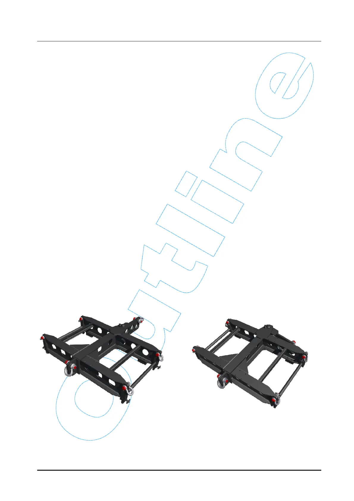
2 DESCRIPTION OF THE RIGGING DEVICE
(FRAME)
The rigging frame is shown in the following illustrations.
Operating configuration. Transport configuration.
Figure 1 – Frame
In a few words, the frame is made up of two main elements that are interconnected via a
pinion, forming the load-beating structure, and a series of accessories, which are:
o a quick-locking pin with button for fixing the cantilever arm;