USER’S MANUAL FOR MAINTENANCE, CONTROL & INSTALLATION OF THE
“OUTLINE GTO ARRAY” – Translation of the original instructions
Page 4/31
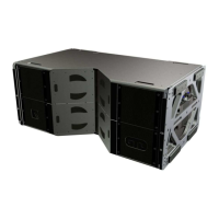
o four brackets and quick-locking pins with buttons for connecting the first element of
the array (GTO loudspeaker enclosure);
o due 6.5 t (centre) shackles and four 3.25 t (side) shackles for hooking on the motor
hoists;
o a shackle for connecting the cable support elements.
Figure 2 - Frame with accessories.
The cantilever beam can be folded away to reduce the hardware’s footprint during
transport; during work, on the other hand, it must be kept extended and locked with the
relative pin (Figure 1).
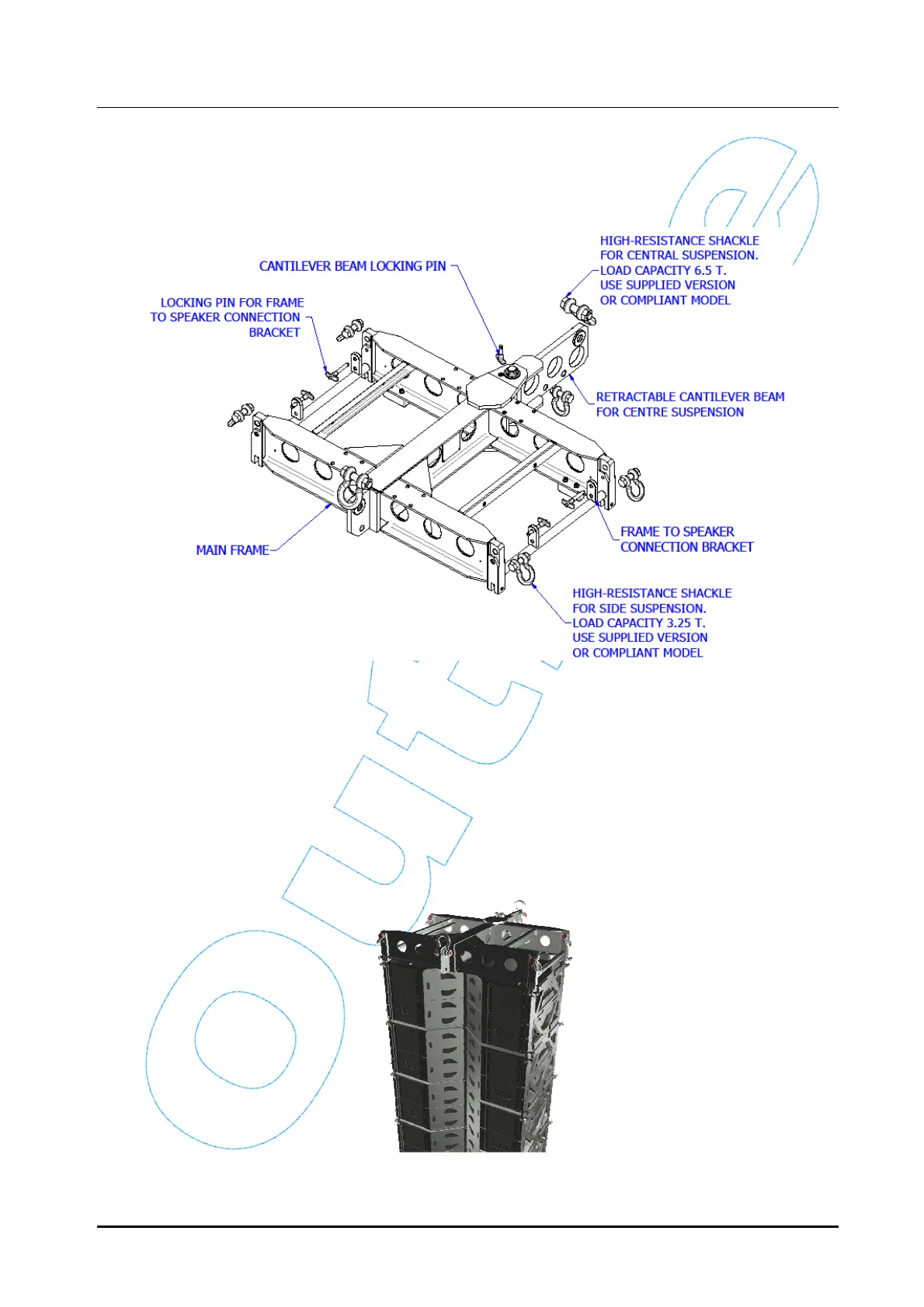
Both the main elements of the frame are constructed by assembling (welding) a series of
specially machined and manufactured in S355JR steel beams and plates. The frame was
conceived for use in Flying configuration, with the loudspeakers (a maximum of twenty-
four “GTO” elements) hung below it.
Figure 3 - Flying Configuration.