EasyManua.ls Logo

Oval Ultra mass MKII Series User Manual

Oval Ultra mass MKII Series
72 pages
To Next Page IconTo Next Page
Page #1 background imageLoading...
Page #1 background image
PRECISION OVAL CORIOLIS FLOWMETER
With integrally or separately mounted transmitter
ULTRA mass MK
Every OVAL product is fabricated, tested, and inspected under stringent quality control before it leaves
our factory.
To derive maximum benefit from the product, we recommend you to be well familiar with the
information and instructions given in this manual before you place it in service and retain this manual
at the field location for ready reference.
Ins. No. L
718
8
E
Sensor Models CN003, CN006, CN010, CN015,
CN025, CN050, CN080
Transmitter Model CT9401
Integrally-mounted Type
Separately-mounted Sensor Unit
Separately-mounted
Transmitter
Sanitary Fitting Type

Table of Contents

Question and Answer IconNeed help?

Do you have a question about the Oval Ultra mass MKII Series and is the answer not in the manual?

Oval Ultra mass MKII Series Specifications

General IconGeneral
BrandOval
ModelUltra mass MKII Series
CategoryMeasuring Instruments
LanguageEnglish

Summary

Getting Started: Before You Begin

Installation Location Precautions

Installation location must ensure accurate and stable measurement, avoiding oscillation.

General Product Information

Detailed Specifications

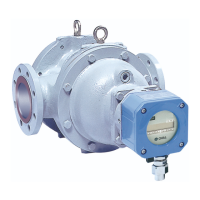
Specifications for sensor units including model, materials, and operating conditions.

Transmitter CT9401 Specifications

Specifications for the CT9401 transmitter including power, environmental, and communication interfaces.

Physical Dimensions and Parts

Integrally Mounted Sensor Dimensions (SUS316L/Hastelloy C)

Provides outline dimensions and weights for integrally mounted SUS316L sensors.

Integrally Mounted Sensor Dimensions (Hastelloy C)

Provides outline dimensions and weights for integrally mounted Hastelloy C sensors.

Separately Mounted Sensor Dimensions (SUS316L/Hastelloy C)

Provides outline dimensions for separately mounted SUS316L sensors.

Separately Mounted Sensor Dimensions (Hastelloy C)

Provides outline dimensions for separately mounted Hastelloy C sensors.

Sanitary Fitting Sensor Dimensions

Details outline dimensions for both integrally and separately mounted sanitary fitting type sensors.

Transmitter CT9401 Dimensions

Provides outline dimensions for the separately mounted CT9401 transmitter.

Installation Procedures

Installation Site Considerations

Factors to consider for selecting an installation location for optimal performance and access.

Ensuring Sensor is Filled

Emphasizes the importance of a completely filled sensor for accurate measurement and zeroing.

Specific Installation Types

Steps for installing flanged type sensors, including flange alignment and bolt tightening.

Flanged Type Installation

Steps for installing flanged type sensors, including flange alignment and bolt tightening.

Sanitary Fitting Type Installation

Procedure for welding companion sleeves and installing sanitary fitting type sensors.

Screw-in Type Installation

Instructions for installing screw-in type sensors using an O-ring.

Changing Transmitter Orientation

Changing Display Orientation

Wiring Connections Guide

Wiring Connection Basics

Instructions for using furnished pressuretight packing for cable entry.

Cable Lead-in Fitting Procedures

Instructions for using furnished pressuretight packing for cable entry.

Power & Output Signal Connections

Details on accessing terminal boards for power and output signal wiring.

Sensor to Transmitter Wiring

Instructions for making wiring connections between the separately mounted transmitter and sensor unit.

Power Supply & Grounding

Connecting power supply lines and proper earth grounding for safety.

Analog Output Wiring

Wiring analog outputs (4-20mA) and suggestions for shielded twisted pair.

Pulse Output Wiring

Wiring pulse outputs and connecting shields for signal integrity.

Terminal Identification: Output & Power

Identifies terminals for output signals and power supply connections.

Terminal ID: Sensor to Transmitter

Identifies terminals for sensor unit to transmitter interconnect cable.

LCD Display Menu Operations

Operating the Flowmeter

Maintenance and Troubleshooting

LinkTop Setup for Liquid Measurement

Related product manuals