Do you have a question about the Oval ALTI mass CA00A and is the answer not in the manual?
Verify product model, serial number, and major ratings on the transmitter nameplate.
Maintain ratings like flowrate, pressure, and temperature within specified limits for accuracy and service life.
Ensure pressure protection, avoid touching hot/cold surfaces, and minimize pipeline oscillation.
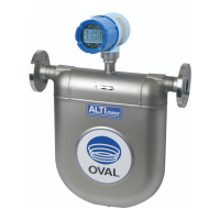
Overview of ALTImass series Coriolis flowmeters with Type U, S, and B models and sophisticated transmitter.
Details specifications for Type U, S, and B sensor units, including materials, connections, and operating limits.
Provides performance data like flowrate accuracy, repeatability, and zero stability for Type U, S, and B models.
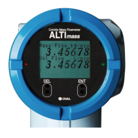
Describes the LCD display modes, switches, and indicators of the transmitter.
Presents pressure loss coefficient graphs for various Type U models based on flowrate and viscosity.
Provides outline dimensions and weights for Type U sensor units, including integral and separately mounted models.
Details outline dimensions and weights for Type S sensor units in stainless steel and titanium tube types.
Presents outline dimensions and weights for Type B sensor units, covering integrally and separately mounted models.
Shows outline dimensions for the separately mounted transmitter, including stanchion mounting details.
Covers general guidelines for selecting a location, avoiding environmental factors, and ensuring proper piping support.
Suggests recommended physical orientations for Type U, S, and B sensors based on fluid type and transmitter orientation.
Advises on avoiding specific installation practices that can cause meter accuracy loss, like locating at the highest point or on pump suction.
Details standard piping conditions, vibration influence, cavitation prevention, and flow considerations.
Explains installation procedures for flange, sanitary fitting, and screw-in types, including torque specifications.
Guides on providing appropriate pipe supports to prevent oscillation and ensure measurement accuracy, emphasizing not supporting the sensor body.
Describes methods for maintaining sensor unit temperature at low or high temperatures using heat retention materials or heat tracers.
Details how to access terminals and make power and output signal connections for both integral and separately mounted models.
Explains connections for power supply lines and the earth ground terminal, emphasizing voltage range compliance.
Provides diagrams and descriptions for transmitter power and output signal wiring, and separately mounted sensor unit wiring.
Step-by-step procedure to change the cable entry orientation of the terminal box on the sensor unit.
Procedure for flushing piping assemblies to remove scale and sludge before sensor unit installation.
Safety check for connecting bolts, gaskets, and flow direction before operation.
Procedure to fill the sensor tube with process fluid and check for leaks from connections.
Procedure to perform a zeroing adjustment when measuring conditions have stabilized and flow is halted.
Explains the components of the transmitter display, including LCD rows, LEDs, and infrared switches.
Covers procedures to access the MODE SELECT menu, view parameters, and understand the transition charts for configuration.
Explains how to enable and set up a password to safeguard transmitter readings and prevent unauthorized parameter changes.
Introduces the self-diagnostic functions for early identification of troubles, covering probe, drive coil, and transmitter checks.
Explains the zeroing function to detect errors and minimize offset drift, detailing methods via LCD switches, status input, or communication.
Details setup for pulse output 1 and 2, including assignment, frequency, flowrate, low cutoff, and error states.
Explains how to configure analog outputs for mass flow, volume flow, density, temperature, and drive output, including assignment and scaling.
Covers assigning status information like error status, flow direction, and alarms to the status output.
Explains assigning functions like pulse/analog output fixed to 0%, zeroing, or totalizer reset to the status input.
Describes setting up high/low alarms for flowrate, temperature, density, and total flow, including alarm types and hysteresis.
Lists error types, descriptions, causes, influences on output, and suggested coping actions for various error conditions.
Details explosionproof specifications (TIIS, ATEX, IECEx, KCs, CSA, EAC, NEPSI, ITRI) for integral and separate types.
Covers safety precautions for explosionproof equipment, cable glands, blanking plugs, insulation, earthing, and dedicated cables.
Explains the explosionproof pertinent information described on the product's label for both sensor and transmitter sides.
Specifies installing the equipment vertically for self-drain and taking countermeasures for rainwater if the conduit faces upward.
Explains the product code structure for Type U models (CA00A to CA250), detailing selector charts for various specifications.
Details the product code structure for Type S models, covering stainless steel and titanium tube types with various specifications.
Explains the product code structure for Type B models, outlining various specifications and their corresponding codes.
Provides explanation for older product codes of Type U models, specifically CA00A to CA080 and CA100 to CA250.
| Brand | Oval |
|---|---|
| Model | ALTI mass CA00A |
| Category | Measuring Instruments |
| Language | English |


 Loading...