L
--
740
--
28
--
E
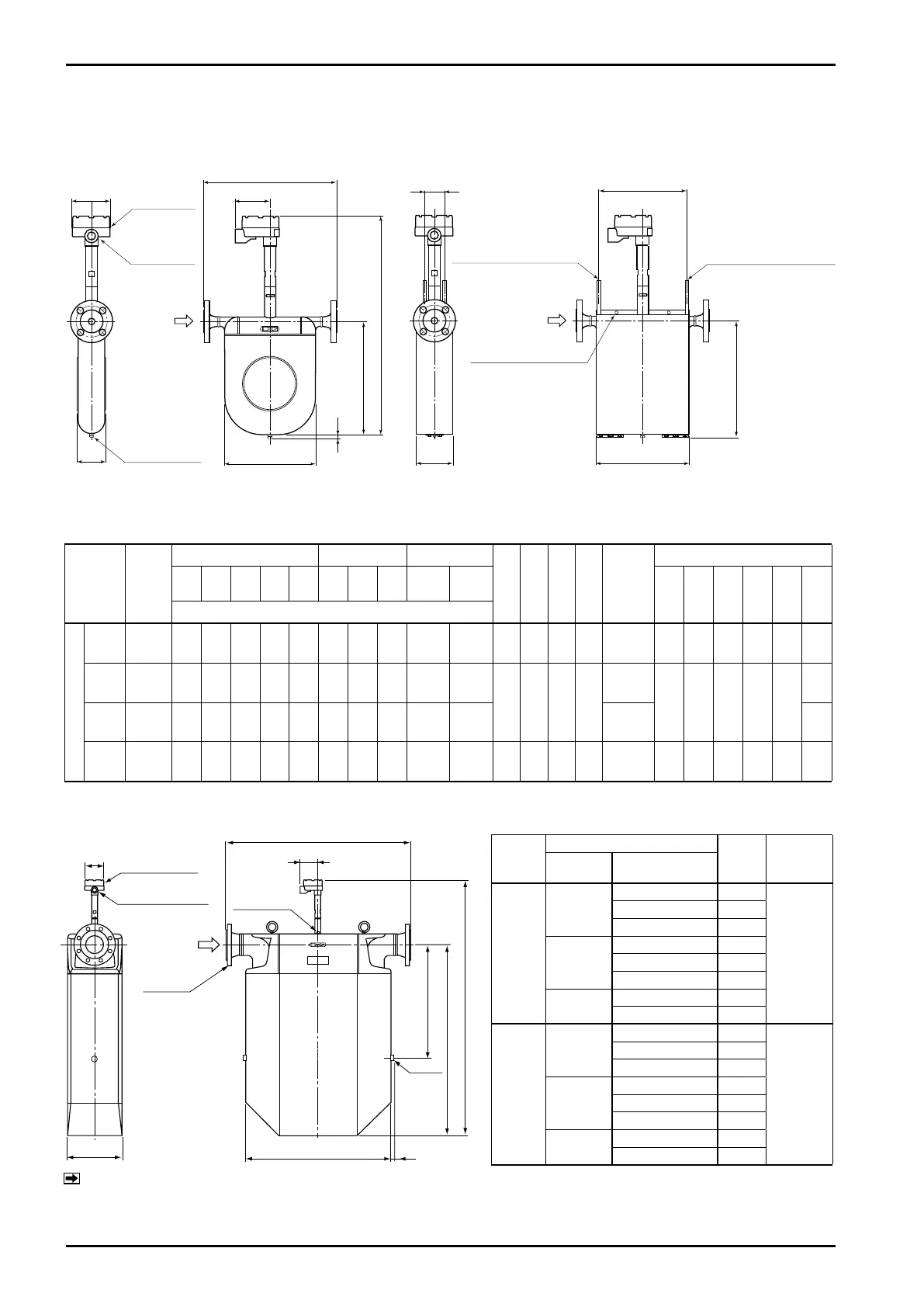
5.1.6 High temperature service models (CA025 to CA150)
Model
Nom.
size
JIS ASME, JPI DIN
H h1 A W
App.
Weight
kg
(JIS 10K)
With Heat Tracer
10K 20K 30K 40K 63K 150 300 600
PN
10, 16
PN
25, 40
Lh h2 Ah A1 Wh
Weight
kg
L
CA025
25
(1″)
380 380 400 400 422 411 424 437 376 380 638 329 83 262 10.9 254 340 106 56 268 16.9
CA040
40
(1・1/2″)
513 513 541 541 585 547 560 575 507 513
768 452 121 385
20.3
376 464 144 70 390
31.8
CA050
50
(2″)
513 523 561 561 595 550 563 582 513 519 20.7 32.2
CA080
80
(3″)
657 675 725 725 771 699 717 737 659 675 960 602 174 510 54.1 501 612 198 110 545 75.1
Transmitter separately mounted type/Flange connection type (CA100, CA150)
A
W
h1
10
H
φ107
φ10stainlesssteelpipe
φ10stainlesssteelpipe
98
L
Ah
Wh
h2
A1
Lh
Heatretentionfluidinlet
Heatretentionfluidoutlet
Forholdingheattracer
M6bolt
Terminalbox
Groundscrew
Cableentry
G3/4
(G1/2 : TIIS)
Flow
direction
Flow
direction
Dimensions in millimeters
Sensor Unit Sensor Unit with Heat Tracer
Fig. 5.9 Outline Dimensions of High Temperature Service Models Sensor Unit
High temp. service models
Model
Flange
L
App. Weight
kg(JIS10K)
Nom.
size
Flange rating
CA100
100
JIS 10K 992
231
JIS 20K 1006
JIS 30K 1016
4″
ASME, JPI 150 1018
ASME, JPI 300 1036
ASME, JPI 600 1082
DN100
PN 10, 16 968
PN 25, 40 994
CA150
150
JIS 10K 1300
246
JIS 20K 1320
JIS 30K 1330
6″
ASME, JPI 150 1318
ASME, JPI 300 1338
ASME, JPI 600 1388
DN150
PN 10, 16 1250
PN 25, 40 1290
Dimensions in millimeters
Transmitter separately mounted type/Flange connection type (CA0250, CA040, CA050, CA080)
300
1387
1015
660
810
98
L
φ107
15
Rc1/4
Terminalbox
Cableentry G3/4
(G1/2 : TIIS)
Flow
direction
Flange
Ground
screw
Boss
NOTE: Approximate weights in the table above are of JIS 10K.
For specifications of other flange ratings, see the approval drawing (or customer's acceptance
specification).