●
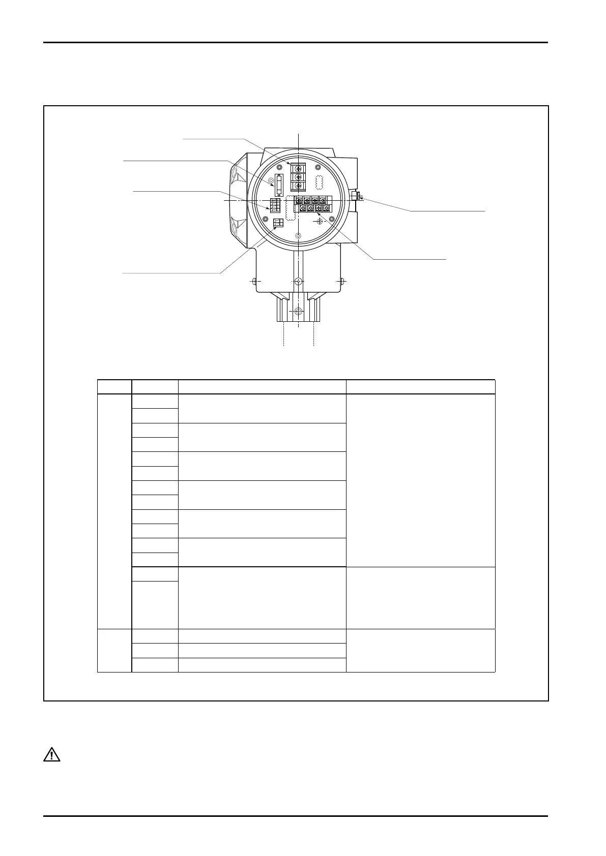
Terminal identification and description
Item Label Description Remarks
Signal
A1(+)
Analog output 1 (4 to 20mA)
1. Max. load resistance is 600Ω
for analog output 1 and 2.
2. Pulse output (voltage
pulse) transmission length is
Max. 10m (at 10kHz)
Max. 100m (at 1kHz)
Max. 1km (at 100Hz)
finished O.D: 0.75sq
3. These input and output signals
are invalid for FOUNDATION
Fieldbus, PROFIBUS PA and
Modbus communications.
A1(-)
A2(+)
Analog output 2 (4 to 20mA)
A2(-)
P1(+)
Pulse output 1
(voltage/open drain output)
P1(-)
P2(+)
Pulse output 2
(voltage/open drain output)
P2(-)
S.I.(+)
Status input (drain input)
S.I.(-)
S.O.(+)
Status output (open drain output)
S.O.(-)
I/O(+)
Expanded in/out
(Modbus communication, etc.)
Modbus communication:Max.trans-
mission length1200m at 0.75sq
FOUNDATION Fieldbus or
PROFIBUS PA communication:
Max. transmission length 1900m at
0.8sq
I/O(-)
Power
L(+) Power (with DC power: +)
GND Earth ground
N(-) Power (with DC power: –)
Fig.7.8
Status in/out terminals
Analog and pulse
output terminals
Power terminals
Replaceable fuse 250V, 2A
Remote output terminals
Ext. GND terminals
L
--
740
--
28
--
E
CAUTION:
7.10 Wiring Diagram
7.10.1 Transmitter power and output signal wiring
Conduct earth grounding work at external ground terminal or "GND" on the power terminal block (Grade
D grounding work).
In case supplying electric power to this flowmeter, do not fail to connect a
protective fuse of rated voltage 2A max.