L
--
740
--
28
--
E
CAUTION
Models CA100 and CA150 weigh approx. 250kg,
CA15H and CA200 weigh 340kg, CA20H and
CA250 weigh 650kg (JIS 10K flange connection).
Obviously, there is high risk with installation
(removal) of this equipment. Therefore, we
suggest you, for safety
,
s sake, to leave this work
to authorized personnel experienced in sling
work and crane operation (observing applicable
regulations).
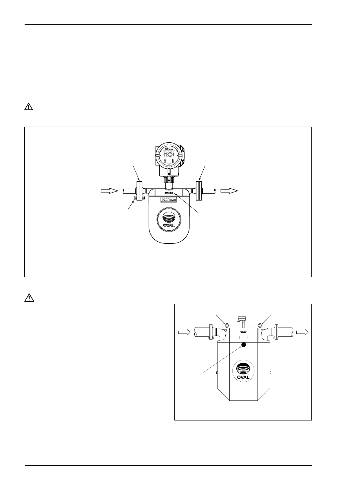
Shown in Fig. 6.13 is the center of gravity of
equipment. When working with a vertical run
in particular, carefully review proper slinging
position, etc. with its weight and center of gravity
in mind.
Incidentally, two M20 (CA100 to CA200) eyebolts*1
(made of SUS304) are installed in the housing
of sensor unit (two places). Since eyebolts can
become loose and come off with time due to
vibration, it is good practice to retighten firmly or
remove upon installation in the piping assembly.
*1: M24 eyebolts are used for CA20H and CA250.
6.5 Installation Guidelines
6.5.1 Flange type
(1) In order to avoid strains on sensor flanges, be sure to correct the flange face-to-face dimension, tilt
and off-center alignment of pipes immediately before and after the sensor.
(2) Make sure of the flow direction by referring to the flow direction plate.
(3) Align the sensor flange O.D. with the flange O.D. of the pipeline, install gaskets, and tighten hex
bolts evenly.
CAUTION: Remove, before installation, protective seals on sensor flanges that are
attached before shipment from factory.
Gasket
※ While Type U meter is used in the figure, the same applies to Types S and B.
IN
Flow Direction Arrow
Fig.6.12
Gasket
OUT
Hex Bolt
Eyebolt Eyebolt
IN OUT
Center
of gravity
Fig. 6.13