L
--
740
--
28
--
E
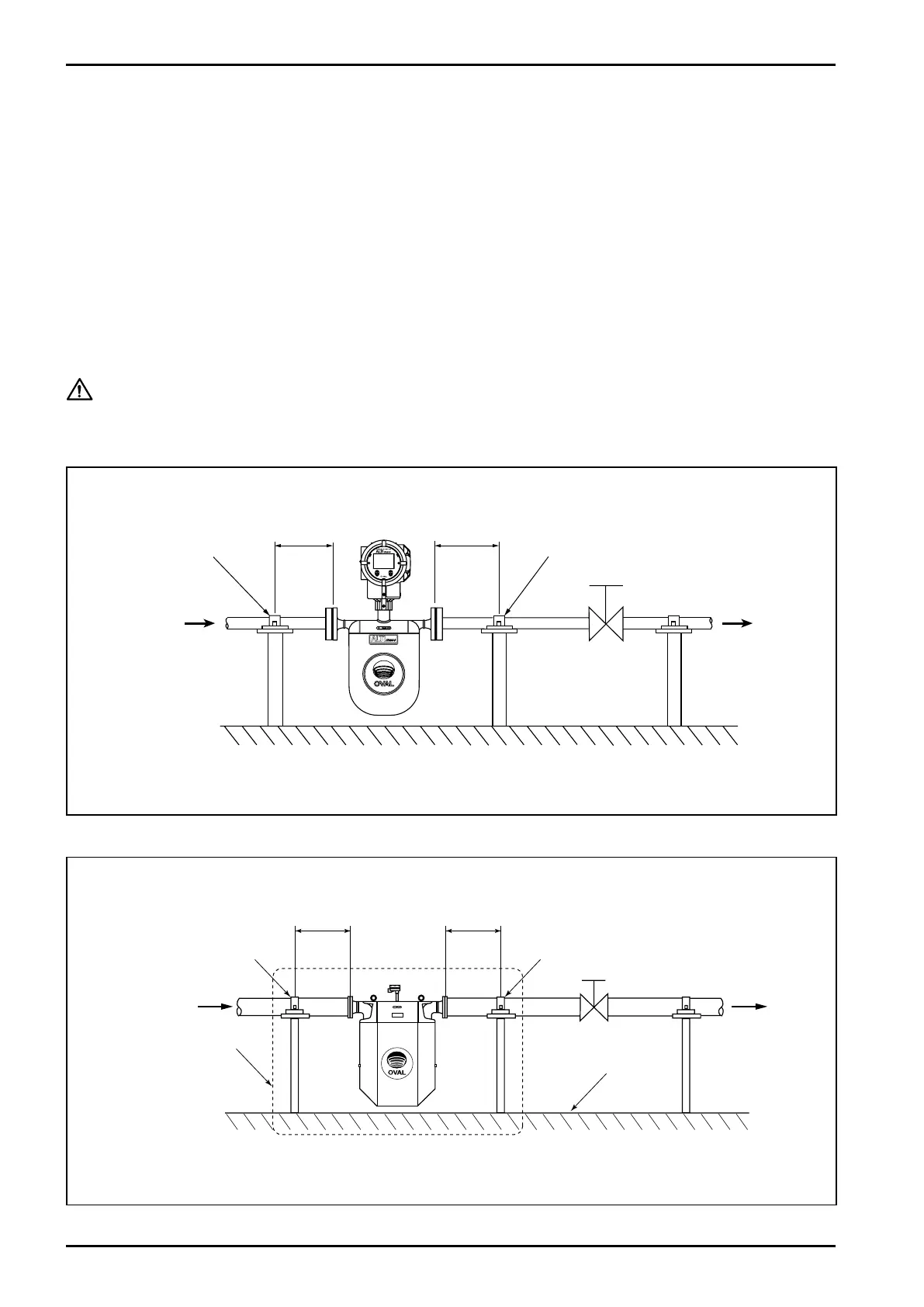
6.6 Installing Proper Pipe Supports
If pipeline oscillation is large or for accurate measurement on low flows, take into account the following:
(1) Provide pipe supports in the range shown below preferably with pipes clamped arranged
symmetrically both upstream and downstream of the sensor.
(2) Clamp the pipeline securely without using rubber bushings or similar cushioning material intended
for the absorption of shock and vibration.
(3) While it is necessary that the rigidity of clamps supporting upstream and downstream piping,
pedestal, floor, etc. that hold individual supporting members be sturdy enough to bear their weight,
it is more important to secure and maintain the overall rigidity of the entire structure. In large sized
installations in particular, changes in the spring elements present in the area surrounded by dot lines
in Fig. 6.18 due to exposure to thermal stress, line pressure, shocks, aging, and other contributing
factors can cause zero shifts.
CAUTION: Support the pipeline with hold-down clamps; never hold down the sensor unit.
6.6.1 Type U pipe supports
●
CA003 to CA080
●
CA100 to CA250
Fig.6.17
Fig.6.18
3 to 20D
3 to 20D
Pipe support
IN OUT
Pipe support
Valve
Pipe support
Pipe support
1.5 to 10D
OUTIN
Valve
D: Nominal pipe size
High rigidity of structure
in the area surrounded
by dot lines is desirable.
Pedestal or floor
D: Nominal pipe size
1.5 to 10D