L
--
740
--
28
--
E
H
C
L
E
φ134
φF
φG
Cableentry
G3/4
230
64
127
60
Flowdirection
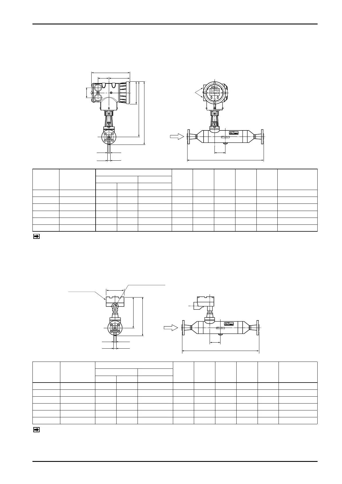
5.2 Type S
5.2.1 Stainless steel tube type (integrally and separately mounted models)
●
Integrally mounted models
H
C
φ
F
L
E
φ
G
Terminalbox
Cableentry
G3/4 (G1/2:TIIS)
φ107
Flowdirection
●
Separately mounted models
Dimensions in millimeters
Model
Nom.
size
L
H C φF φG E
App. Weight
kg (JIS 10K)
JIS ASME/JPI
10K 20K 150
CS010 15(1/2˝) 426 452 458 390 340 5 16.8 69 10
CS015 15(1/2˝) 464 490 496 390 340 7.4 16.8 80 11
CS025 25(1˝) 529 555 570 423 353 12.4 26.6 88 18
CS040 40(1・1/2˝) 716 733 749 439 359 17.8 40.4 112 28
CS050 50(2˝) 882 906 919 474 372 26.4 52.6 153 38
CS080 80(3˝) 1032 1046 1073 510 392 38 77.8 176 69
Fig. 5.15 Outline Dimensions of Integrally Mounted Model
Dimensions in millimeters
Model
Nom.
size
L
H C φF φG E
App. Weight
kg (JIS 10K)
JIS ASME/JPI
10K 20K 150
CS010 15(1/2˝)
426
452
458
246 197 5 16.8 69 7
CS015 15(1/2˝)
464
490
496
246 197 7.4 16.8 80 8
CS025 25(1˝)
529
555
570
280 210 12.4 26.6 88 15
CS040 40(1・1/2˝)
716
733
749
296 216 17.8 40.4 112 25
CS050 50(2˝)
882
906
919
332 229 26.4 52.6 153 35
CS080 80(3˝)
1032
1046
1073
367 249 38 77.8 176 66
Fig. 5.16 Outline Dimensions of Separately Mounted Sensor Unit
NOTE: Approximate weights in the table above are of JIS 10K.
For specifications of other flange ratings, see the approval drawing (or customer
,
s acceptance
specification).
NOTE: Approximate weights in the table above are of JIS 10K.
For specifications of other flange ratings, see the approval drawing (or customer
,
s acceptance
specification).