L
--
740
--
28
--
E
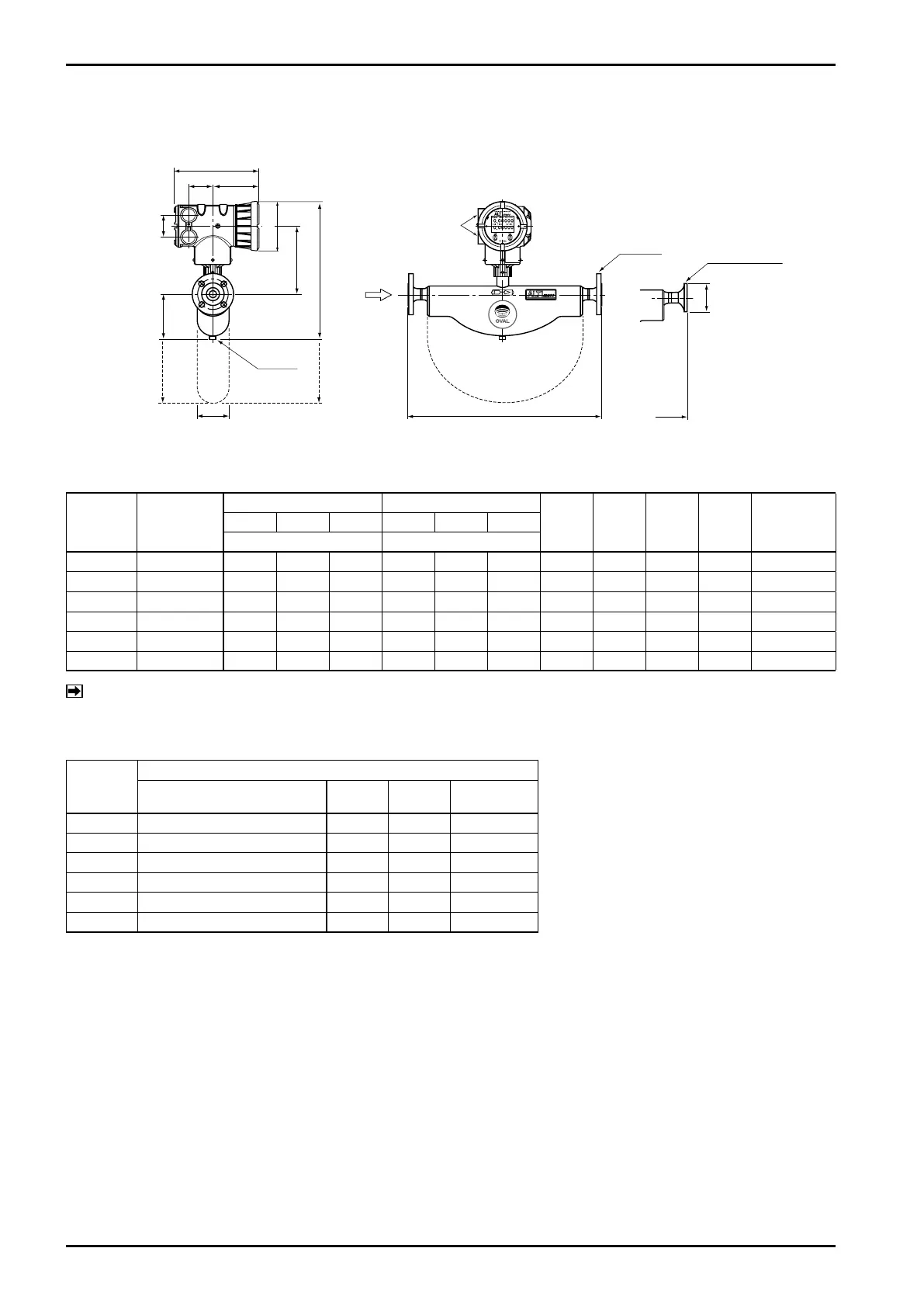
5.3 Type B
5.3.1 Integrally mounted models
h1
h2
H
A
230
64 127
(h1)
(H)
φ134
Cableentry
G3/4
60
Ground
screw
Flow
direction
L
Flange
Ferrulefitting
φD
L
※: Dotted lines show sensor unit envelops of CB040 and 050.
Dimensions in millimeters
Model Nom. size
JIS ASME/JPI
H h1 h2 A
App. Weight
kg
(JIS 10K)
10K 20K 30K 150 300 600
L L
CB006 10(1/2˝) 343 343 361 369 378 390.5 354 94 192 59 7.3
CB010 15(1/2˝) 380 380 400 406 415 427.5 350 94 189 59 7.6
CB015 15(1/2˝) 486 486 506 512 521 533.5 441 168 206 91 11.6
CB025 25(1˝) 569 569 589 601 613 626 436 175 194 91 14.2
CB040 40(1・1/2˝) 626 626 654 660 673 688.5 588 323 197 125 32.8
CB050 50(2˝) 626 636 674 663 676 695 588 323 197 125 33.2
NOTE: Approximate weights in the table above are of JIS 10K.
For specifications of other flange ratings, see the approval drawing (or customer
,
s acceptance
specification).
Model
Ferrule fitting
Process connection L φD
App. Weight
(kg)
CB006 Ferrule 10A 333 34 5.2
CB010 Ferrule 15A 380 34 6.1
CB015 Ferrule 15A 476 34 9.9
CB025 Ferrule 25 (ISO), IDF 1S 559 50.5 11.1
CB040 Ferrule 38 (ISO), IDF 1.5S 606 50.5 29.3
CB050 Ferrule 51 (ISO), IDF 2S 606 64 29.3
Process connection: A in mm; S (sanitary) in inches.
Fig. 5.21 Outline Dimensions of Integrally Mounted Model