L
--
740
--
28
--
E
1
230
98
210
237
179
30
143
φ107
16
175 63
37
R1/4Processconnection
Mainbody
Flowdirectionarrow
Groundscrew
Terminalbox
4-φ9Fittinghole
(FitsM8bolt.)
Cableentry
G3/4
(G1/2 : TIIS)
52
Flowdirection
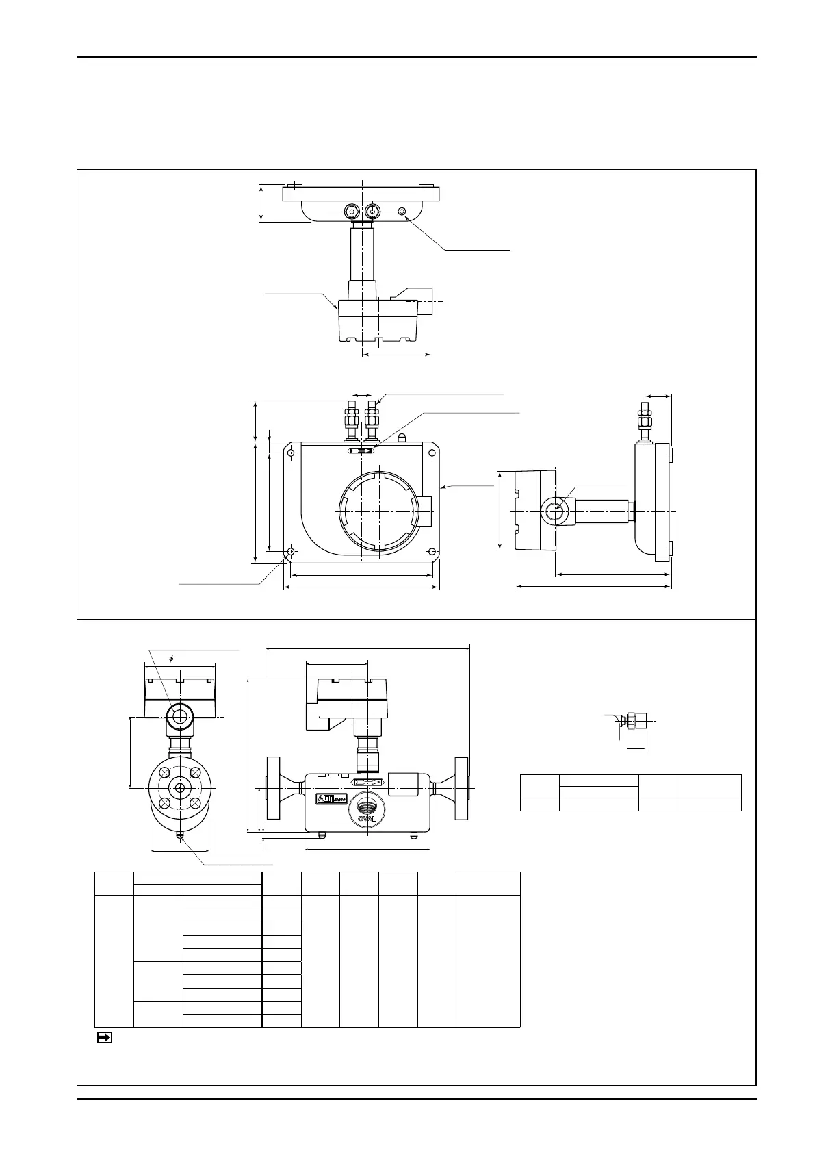
5. PART NAMES AND OUTLINE DIMENSIONS
5.1 Type U
5.1.1 CA00A, CA001 and CA003 (separately mounted models)
Fig. 5.2 Outline Dimensions of Sensor Unit (CA003)
Dimensions in millimeters
Model
Flange
L H h1 A W
App. Weight
kg (JIS 10K)
Nom. size Flange rating
CA00
10
JIS 10K
0
.1 1 .0
JIS 0K
JIS 0K
JIS 0K
JIS K 1
1/″
ASME, JPI 10
01
ASME, JPI 00
10
ASME, JPI 00
DN1
PN 10, 1
PN , 0
1
Model
Screw conn.
L
App. Weight
kg (JIS 10K)
Flange rating
CA00
Rc/
.
Fig. 5.1 Outline Dimensions of Sensor Unit (CA00A and CA001)
Approx. weight: 9 kg
Cableentry
G3/4(G1/2:TIIS)
Groundscrew
L
A
W
98
H
109
h1
10
107
L
A
W
98
H
109
h1
10
107
L
φD
Cableentry
G3/4
Groundscrew
Screw-in type
※: This table is applied to material
code S and M. In case of code H,
please consult our representative.
※: Flange size for model CA00 is
1/" in case of ASME or JPI.
※: As long as flange O.D. and bolt
holes remain the same while flange
r a t i n g m a y d i ff e r, t he f l a n g e
thickness with the higher rating is
chosen in the above.
※: DIN flanges are available only to
meters of the material code, "S"
and "M".
NOTE: A
pproximate weights in the table above are of JIS 10K.
For specifications of other flange ratings, see the approval drawing (or customer
,
s acceptance specification).