L
--
740
--
28
--
E
7.4 Pulse Output Wiring
When pulse output is to be connected to a receiving instrument, Pulse Output 1 has terminals P1 (+) and
terminal P1 (-) while Pulse Output 2 has terminal P2 (+) and terminal P2 (-).
If voltage pulse signal is your option, signal transmission length has restrictions on output frequency.
Output frequency Max. transmission length ※
10kHz 10m
1kHz 100m
100Hz 1000m
※ Values are based on wire material 0.75 sq in cross section.
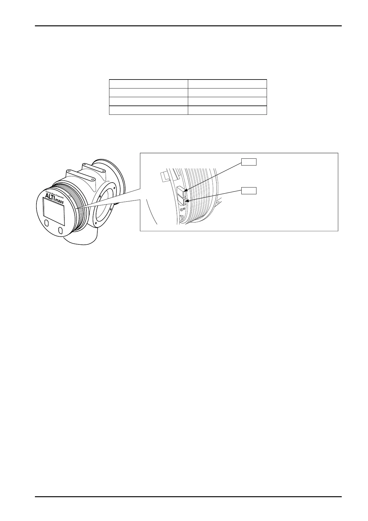
To change from voltage pulse output to open drain pulse output, or vice versa, remove the front lid and
select jumper positions as indicated below.
Pulse output 1 jumper
OPEN: Open drain pulse
CLOSE: Voltage pulse
JP3
Pulse output 2 jumper
OPEN: Open drain pulse
CLOSE: Voltage pulse
JP4
7.5 Status Output Wiring
Status output appears across terminals S.O. (+) and S.O. (-).
Status output setup procedure appears in 9.7.3 Status output.
※ Status output will be invalid if FOUNDATION Fieldbus, PROFIBUS PA is selected as communication
interface.
Pulse output setup procedure appears in 9.7.2 Analog output.
※ Pulse output will be invalid if FOUNDATION Fieldbus, PROFIBUS PA is selected as communication
interface.
Fig.7.7