L
--
740
--
28
--
E
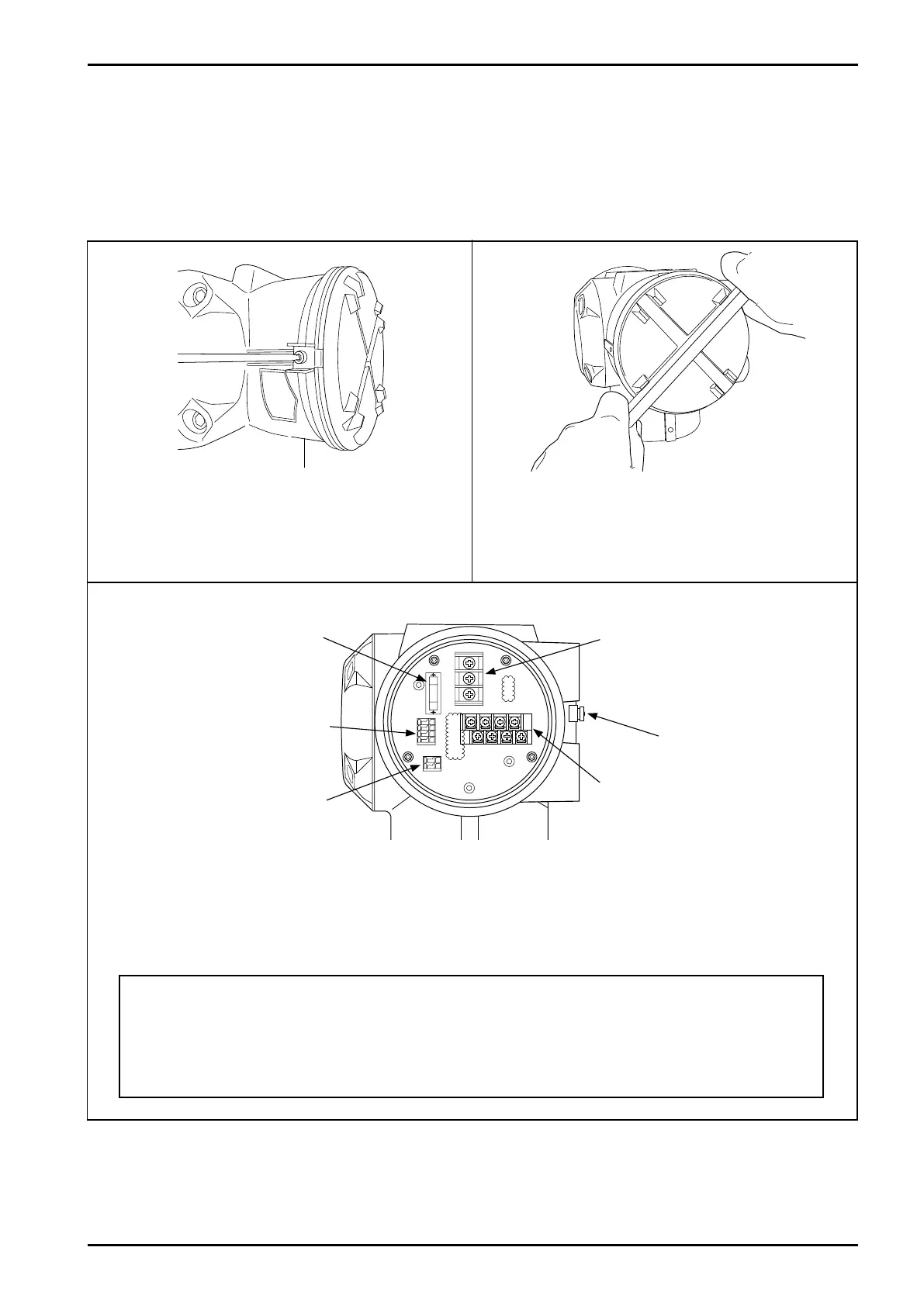
7.1.1 Power and output signal connections (both integrally and separately mounted models)
(1) Terminals for wiring connections are found at the back of transmitter housing. Remove the cover
and make wiring connections.
① Using hex wrench, take off latch fitting screw (M3 hex
socket head).
② Using a flat tool, slowly turn the terminal box lid
counterclockwise to loosen and then loosen by hand.
(Use care to avoid damaging the finish.)
③ Removing the terminal box cover provides access to the cable entry and the power board
holding the power and output signal terminal blocks. The customer is to furnish crimp style
terminals required for power and output signal wiring connections.
Status input/output
terminal block
Communication signal
terminal block
Power terminal block
(M4 screws)
Analog output and pulse
output terminal block (M3.5
screws)
Power terminal block for crimp terminals: Round shaped 8.1mm max. O.D. for M4
Output signal terminal block for crimp terminals: Round shaped 7.2mm max. O.D. for M3.5
Status in/out terminal block and communication signal terminal block are of screwless type
and require no crimp style terminals.
Fig.7.1 Fig.7.2
Fig.7.3
7. WIRING INSTRUCTIONS
7.1 Wiring Connections
Replaceable fuse
0V, A
Ext. GND terminals