L
--
740
--
28
--
E
CAUTION: When tightening the display lid, tighten securely using a flat tool or similar
instrument. Insufficient tightening can affect gas-tightness and sensitivity of
display
,
s optical switch.
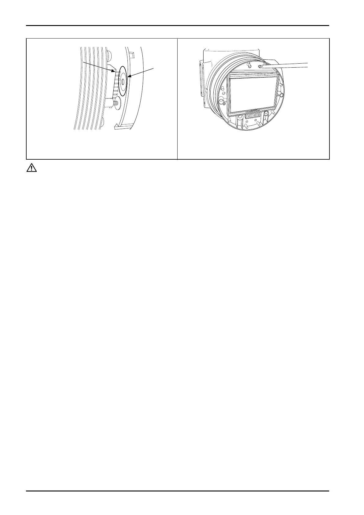
⑦ Align connector pins (male) on the transmitter with
mating through holes (female) in the display unit.
⑧ Tighten screws (3 places) at new screw holes and re-
install into the original position.
Connector
pins
Display
unit
through
holes
Fig.6.38Fig.6.37
Depending on
the transmitter
type, shapes of
the connector or
peripheral parts
may be different.