WARNING WARNING
PRIOR TO WINDING OR MAKING ADJUSTMENTS TO THE SPRINGS, EN-
SURE YOU’RE WINDING IN THE PROPER DIRECTION AS STATED IN THE
INSTALLATION INSTRUCTIONS. OTHERWISE, THE SPRING FITTINGS MAY
RELEASE FROM SPRING IF NOT WOUND IN THE PROPER DIRECTION AND
COULD RESULT IN SEVERE OR FATAL INJURY.
IMPORTANT: RIGHT AND LEFT HAND IS ALWAYS DETERMINED FROM INSIDE THE BUILDING
LOOKING OUT.
Tools Required
• Power drill
• Drill bits: 1/8”,
3/16”, 9/32”, 7/16”,
1/2”
• Ratchet wrench
• Socket driver: 7/16”
• Sockets: 7/16”,
1/2”, 9/16”, 5/8”
• Phillips head
screwdriver
• Locking Pliers
• (2) Vice clamps
• Wrenches: 3/8”,
7/16”, 1/2”, 9/16”,
5/8”
• 1/4” Torx bit
• Approved winding
rods
• Hammer
• Tape measure
• Step Ladder
• Level
• Pencil
• Leather gloves
• Safety glasses
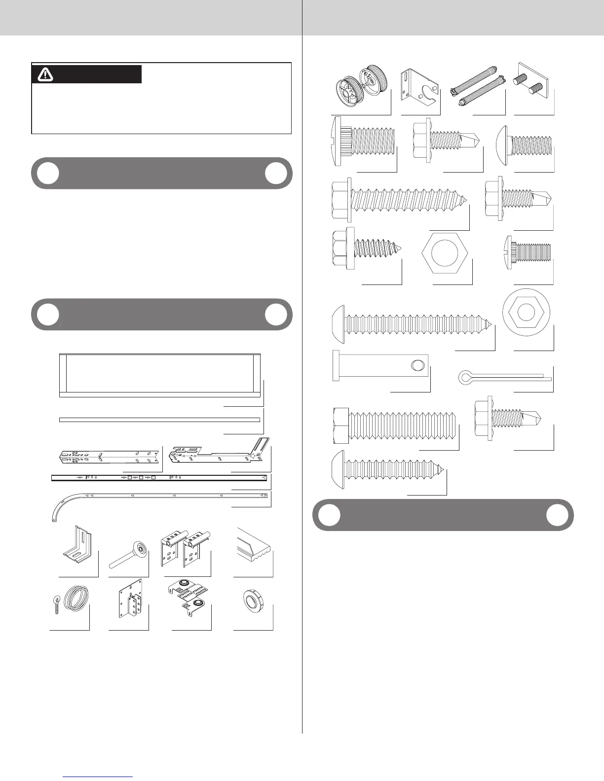
Package Contents
NOTE: Depending on the door model, some parts listed will not be supplied if not required.
Rear Back Hangs may not be included with your door.
Door sections (as required)
Torsion shaft
Vertical tracks RH/LH
(2) Horizontal track angles (as required)
Horizontal tracks RH/LH
F.A. flag angles RH/LH (as required)
Weather seals & nails
(If included)
F.A. jamb brackets
(as required)
Drawbar operator
bracket (if included)
(2) Top fixtures
Track rollers
Pull down rope
(if included)
(2) End bearing
brackets
Center bracket
bushing
Cable drums RH/LH Torsion springs RH/LH
1/4”-20 x 7/8” Self
drilling screws (as required)
Center bracket
(2) 3/8”-16 x 3/4”
Truss head bolts
Stud Plate
(as required)
(4) 1/4”-20 x 5/8”
Carriage bolts
5/16” x 1 5/8” Hex head lag screws
(as required)
(2) 3/8”- 16 Hex nuts
1/4”-20 x 5/8” Self
drilling screws (as required)
1/4”-14 x 5/8” Self tapping
screws (as required)
1/4”-20 x 9/16”
Track bolts (as required)
1/4”- 20 Flanged
hex nuts (as required)
5/16” x 2” Tamper-resistant hex head
lag screw (as required)
5/16” x 1-1/4”
Clevis pin
Cotter pin
(2) 3/8”-16 x 1-1/2” Hex bolts
5/16” x 1-5/8” Tamper-resistant
hex head lag screws (as required)
1/4”-20 x 11/16” Self
drilling screws (as required)
Door Section Identification
Graduated end and center hinges are always pre-attached at the top of each section (except
top section) and the graduated end hinges are stamped for identification, #1, #2, #3, and #4
(#4 only on five section doors). The stamp identifies the stacking sequence of the section.
The sequence is always determined by #1 being the bottom section to #3 or #4 being the
highest intermediate section. If the stamp on the graduated end hinge is illegible, refer to
the section side view illustration. The section side view illustration shows the graduated end
hinge profile of all sections, and can also be used to identify each section.
The BOTTOM SECTION can be identified by #1 graduated end hinges, the factory attached
bottom astragal and by the factory attached bottom corner brackets.
The LOCK SECTION can be identified by #2 graduated end hinges on a 4 section high door
and by #3 graduated end hinges on a 3 section high door.
The INTERMEDIATE SECTION can be identified by #3 graduated end hinges (Only on a 4
section high door).
NOTE: #4 graduated end hinges are used on the fourth section of five section doors.
The TOP SECTION can be identified with no pre-installed graduated end or center hinges.
4
Please Do Not Return This Product To The Store. Contact your local Overhead Door Ribbon Distributor. To find your local Overhead Door Ribbon
Distributor, refer to your local yellow pages business listings or go to the Find a Ribbon Distributor section online at www.OverheadDoor.com.





 To Next Page