Please Do Not Return This Product To The Store. Contact your local Overhead Door Ribbon Distributor. To find your local Overhead Door Ribbon
Distributor, refer to your local yellow pages business listings or go to the Find a Ribbon Distributor section online at www.OverheadDoor.com.
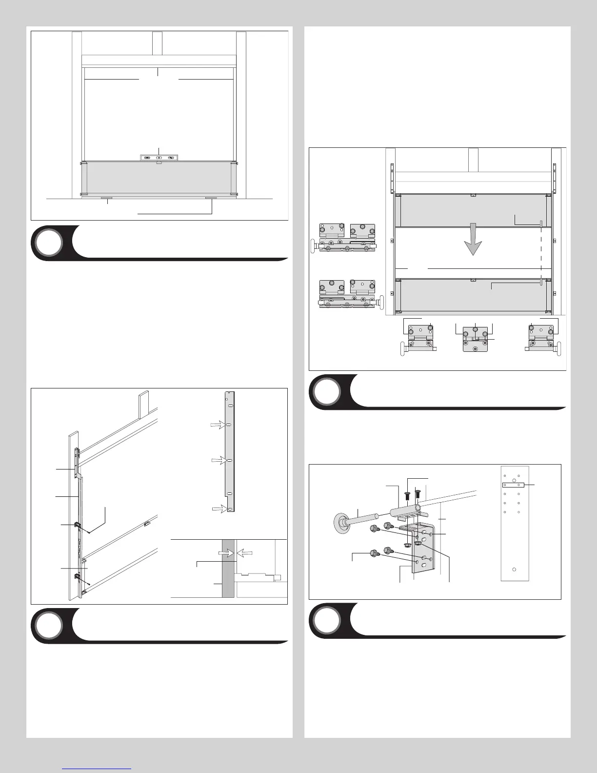
Weather seal
Level
Bottom section
Wooden shims
(If necessary)
Vertical Tracks
6
Tools: Power Drill, 3/16” Drill bit, 7/16” Socket driver, Tape measure,
Level, Step ladder
IMPORTANT: IF YOUR DOOR IS TO BE INSTALLED PRIOR TO A FINISHING CONSTRUCTION
OF THE BUILDING’S FLOOR, THE VERTICAL TRACKS AND THE DOOR BOTTOM SECTION
ASSEMBLY SHOULD BE INSTALLED SUCH THAT WHEN THE FLOOR IS CONSTRUCTED, NO
DOOR OR TRACK PARTS ARE TRAPPED IN THE FLOOR CONSTRUCTION.
IMPORTANT: THE TOPS OF THE VERTICAL TRACKS MUST BE LEVEL FROM SIDE TO SIDE.
IF THE BOTTOM SECTION WAS SHIMMED TO LEVEL IT, THE VERTICAL TRACK ON THE
SHIMMED SIDE MUST BE RAISED THE HEIGHT OF THE SHIM.
Position the left hand vertical track assembly over the rollers of the bottom section. Make
sure the counterbalance cable is located between the rollers and the door jamb. Drill 3/16”
pilot holes into the door jamb for the lag screws.
Loosely fasten jamb brackets and flag angle to the jamb using 5/16” x 1-5/8” lag screws.
Tighten lag screws, securing the bottom jamb bracket to jamb, maintain 3/8” to 5/8” spacing
as shown between the bottom section and vertical track. Hang counterbalance cable over
flag angle. Repeat for other side.
Vertical
track
Jamb
bracket
Flag
angle
Flag angle lag screw locations
5/16” x 1-5/8”
Lag screws
Bottom
section
3/8” to 5/8”
Spacing
Bottom section
Vertical track
15” Radius
Stacking Sections
7
Tools: Power drill,7/16” Socket driver
NOTE: The sections can be identified by the graduation of the factory installed end hinges.
The smallest graduated end hinge on section should be stacked on top of the bottom section,
with each graduated end hinge increasing as the sections are stacked, see Parts Breakdown
on page 2.
NOTE: Make sure graduated end and center hinges are flipped down, when stacking another
section on top.
NOTE: Larger doors will use long stem track rollers with double graduated end hinges.
Place track rollers into graduated end hinges of remaining sections.
With assistance, lift second section and guide the track rollers into the vertical tracks. Lower
section until it is seated against bottom section. Align vertical marks in the upper alignment
sticker, with the lower alignment sticker on right hand side, on the back of door. Keep sec-
tions aligned and fasten center hinge(s) first; then end hinges last using 1/4”-14 x 5/8” self
tapping screws.
NOTE: To prevent center hinge leaf(s) from rotating, first secure the top middle hole of the
center hinge leaf with one 1/4” – 14 x 5/8” self-tapping screw then secure the other two
holes.
NOTE: Larger doors with double graduated end hinges, fasten both hinges to connect the
sections using 1/4” - 14 x 5/8” self-tapping screws.
Repeat same process for other sections, except top section.
IMPORTANT: PUSH & HOLD THE HINGE LEAFS SECURELY AGAINST THE SECTIONS WHILE
SECURING WITH 1/4”-14 X 5/8” SELF TAPPING SCREWS. THERE SHOULD BE NO GAP
BETWEEN THE HINGE LEAFS AND THE SECTIONS.
Lock section
Vertical
tracks
Alignment
sticker
Alignment
sticker
Center
hinge(s)
Left graduated end hinge
with short stem track roller
Left double graduated
end hinge with long
stem track roller
Right graduated end hinge
with short stem track roller
Right double graduated
end hinge with long
stem track roller
1/4”-14 x 5/8” Self tapping screw locations
Secure top
middle
hole first
P/N # 327985 NEW 9-04-06P/N # 327985 NEW 9-04-06
Top Fixtures
8
Tools: Power drill, 7/16” Socket driver
To install the top fixtures, align the top holes in the top fixture base with the second set of
holes in the end cap of the top section. Fasten to section using (4) 1/4”-14 x 5/8” self tap-
ping screws. Secure the top fixture slide to the fixture base loosely using (2) 1/4”-20 x 5/8”
carriage bolts and (2) 1/4”-20 flange hex nuts. The top fixture slide will be tightened and
adjusted later, in step, Adjusting Top Fixture. Insert track roller into top fixture slide. Repeat for
other side.
(4) 1/4”- 14 x 5/8”
Self-tapping screws
Short stem track roller
Top fixture base
Top fixture slide
(2) 1/4”- 20
Flange hex nuts
Top section
2nd Set
End cap
(2) 1/4”- 20 x 5/8”
Carriage bolts
2nd Set
Endcap hole pattern
Operator Bracket
9
Tools: Power drill, 7/16” Socket driver, Phillips head screwdriver, Vice
clamps, Tape measure
NOTE: If installing a trolley type operator, complete this step. If not, skip this step and
continue with next step.
IMPORTANT: WHEN INSTALLING A TROLLEY TYPE OPERATOR ON THIS DOOR, AN OVER-
HEAD DOOR TROLLEY BRACKET MUST BE SECURELY ATTACHED TO THE TOP SECTION. IT
IS THEN UNNECESSARY TO FURTHER REINFORCE THE TOP SECTION OF THIS DOOR, WHEN
ATTACHING A TROLLEY TYPE OPERATOR, AS LONG AS THE INSTALLATION OF THE OPERA-
TOR IS ACCORDING TO INSTALLATION INSTRUCTIONS AND OWNER’S MANUAL AND FORCE
SETTINGS ARE ADJUSTED PROPERLY.
Remove, but retain (4-6) 1/4” – 20 x 7/8” self drilling screws from the center of the strut,
allowing the operator bracket to slide between the section and the strut.
7





 To Next Page