%&'"()*+,,-,,.".
ON/OFF: Power Control Input signal. Leave open for ON, Connect to ground
for OFF. Use an open collector transistor or switch to ground, but do not drive
high. This input will turn the unit ON or OFF. When running from battery back-
up, this signal can only be used to turn the unit OFF. If the signal is then
released and there is no power on Vin, then the unit will remain OFF.
&+&0. 67(86(,-9
The owa4x provides up to 10 configurable digital Input/Outputs, from DIO0 to
DIO9.
These pins can be configured as inputs or as outputs. Note that if the pin is
configured as an output it cannot be used as an input, and may be damaged if
a voltage is applied while it is configured as an output. Hence ensure that the
corresponding output pin is OFF before using it as an input. See the
programming guide for more details.
The digital inputs are not TTL compatible, and they can withstand inputs up to
50V so that sensors and switches with higher voltages can be used. For
example, in an automotive application, a switch may be connected to the
positive supply giving an input of 14V or 28V. The input impedance is 180K,
except for DIN0 with 220K and DIN6, which has 1K to +5V.
All inputs are inverted except DIO6, which is ready to take a iButton on it, and
the range is also different when using this pin as input (see connector table).
If the digital output is set to 1 in the software it will be OFF and the transistor will
pull the output pin to ground giving a low level. If it is set to 0 in the software it
will be ON and the transistor will be open. Note that there are no pull-ups on
these pins so to obtain a high level when the output is ON requires an external
pull-up to a positive supply.
The DIO0 to DIO7 outputs are open collector transistor type capable of
switching up to 50V and sinking up to 100mA. Do not place a load that will draw
more than 200mA or damage to the unit may result.
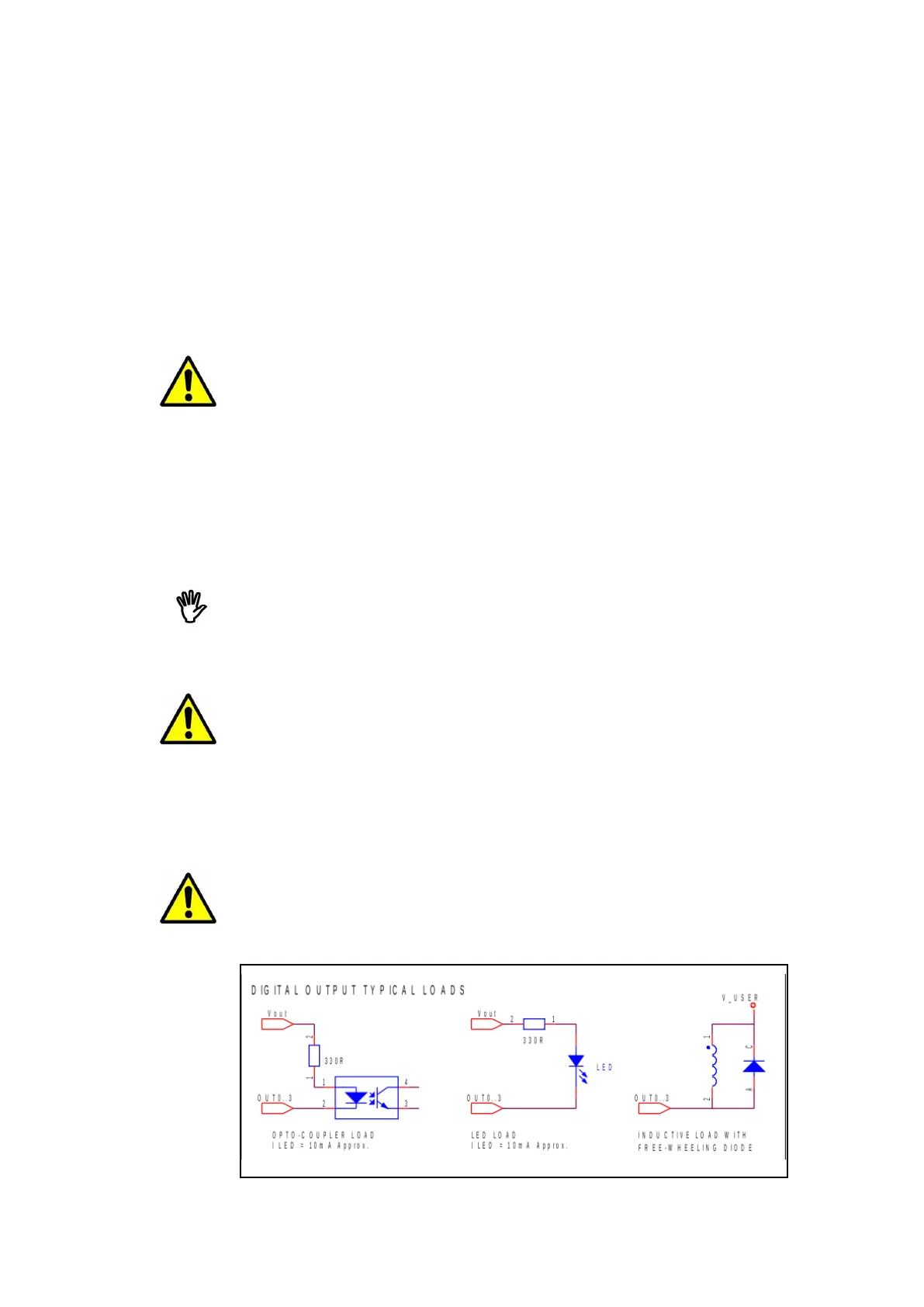
With these open collector outputs the load should be connected between the
output pin and a positive supply. The positive supply could be provided by the
user, or from the pin Vout (pin 23). The maximum output current from Vout is
500mA, which should be sufficient to drive up to 8 LEDs, Opto-couplers or Solid
State Relays at 10-12mA each. A typical connection for one output is shown
below.
For an inductive load (such as a relay or motor) it is mandatory to connect a
free-wheeling diode to provide a return path to the supply for the inductive
energy, as shown below. Otherwise the resulting voltage spikes during switch
off could damage the output circuitry.
.3