%&'"()*+,,-,,.".
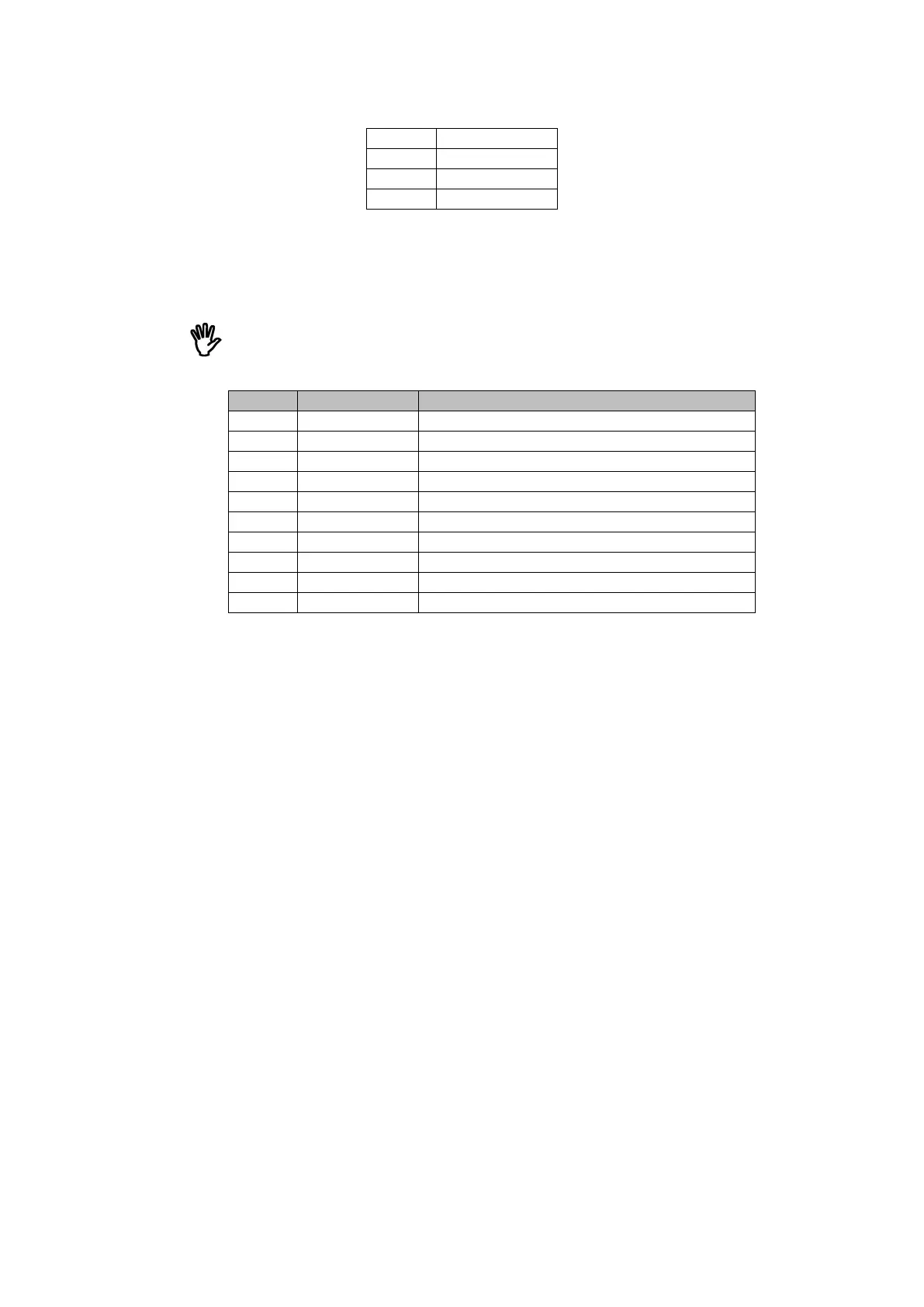
J4-7 CANH2
J4-8 GND
J4-9 CANL1
J4-10 CANH1
3.5 Connector J4 of DK
Note that to use RS485 or CAN, a 120Ω termination resistor must be placed at
each end of the network. In the development kit there is a termination resistor of
120 ohms soldered for each of the buses.
:
Pin Signal Function
J5-1 TXD-4 TX UART4 (Main uart)
J5-2 RXD-4 RX UART4 (Main uart)
J5-3 TXD-5/RTS-4 TX UART 5
J5-4
RX UART 5
J5-5 TXD-1 TX UART1
J5-6 RXD-1 RX UART1
J5-7 V_OUT +5V voltage output 500mA MAX
J5-8 ON/OFF Connect to ground to power down
J5-9 V_IN Power input
J5-10 GND Ground
3.6 Connector J2 of UDK
RS232 interface signals of the UART4 go to J6 DB9 connector too.
J7, J8, J9, J10, J11 connectors are directly connected to signals coming from
the owa4x connectors in order to connect external devices or signal sources.
$4)'5
This section describes the owa4X development kit components connections.
The steps for mounting the components in owa4X are the following:
Antennas: Connect the antennas used for the application, 3G, GNSS etc.
DB9 RS-232 Serial connector: Connect a RS232 connector, or USB to RS232
connetor to the PC to debug the unit.
Owa4x Signals: Connect the signals needed to the development kit in the
connectors J1 to J5. The development kit has specific use for each of the signal
in each of the connections. DIOs should be connected to the DIN or DOUT
depending on which feature is to be tested. RJ11 cable:
microSIM card: The microSIM card should be introduced in the SIM card
compartment. The SIM card contacts shall be faced upwards. Push the SIM
card until hearing a click and then lock it with the flap.
AC/DC Power supply: Provided AC/DC power supply adaptor can be
connected to developers board, connector X3, and to a suitable AC main outlet.
Alternatively a laboratory power supply can be connected to V_IN and GND at
J7 connector.
+-
 Loading...