%&'"()*+,,-,,.".
3.2 Connector J1 of DK
Microphone and speaker signals are connected to Jacks for the microphone
and speaker connection.
Analog inputs are connected to potentiometers through switches. The switches
should be in OFF position if external signal sources are to be applied.
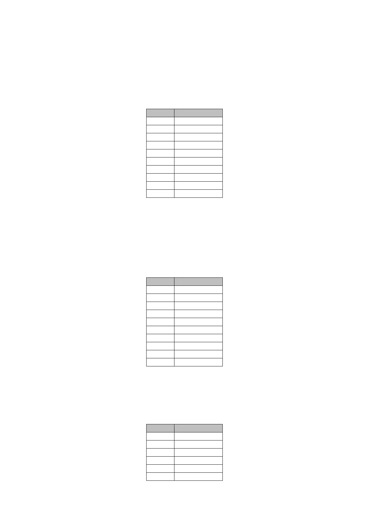
Pin Signal
J2-1 DIN-9
J2-2 DIN-8
J2-3 DIN-7
J2-4 DIN-6
J2-5 DIN-5
J2-6 DIN-4
J2-7 DIN-3
J2-8 DIN-2
J2-9 DIN-1
J2-10 DIN-0
3.3 Connector J2 of DK
Digital inputs have pull downs in the Development kit and a switch to connect to
a high level for the input testing.
Digital input 6 is inverted, so it has a pull up by default, and the switch connects
the input to GND.
If external signal sources are to be connected the switches should be in OFF
state.
Pin Signal
J3-1 OUT-9(HS)
J3-2 OUT-8(HS)
J3-3 OUT-7
J3-4 OUT-6
J3-5 OUT-5
J3-6 OUT-4
J3-7 OUT-3
J3-8 OUT-2
J3-9 OUT-1
J3-10 OUT-0
3.4 Connector J3 of DK
Digital outputs 0 to 7 are open drain, so they give a low value when active.
Digital outputs 8 and 9 are High side so they provide a high value (V_IN) when
active. All the signals have LEDs to provide a visual indication of the status of
the output. The LED will be on when the output is activated.
Pin Signal
J4-1 RS485B
J4-2 RS485A
J4-3 GND
J4-4 KLINE_2
J4-5 KLINE_1
J4-6 CANL2
+3
 Loading...