41
DRAWING TITTLE:
DRAWING NUMBER:
SCALE: SIZE: SHEE T:
DR AWN BY :
APPROVED:
DATE:
REVISION:
CONTROLLER:
IP
2021-04-20 NTS 8" x 11.5" 1 of 1
028-05-0012-04
1.0
OJ
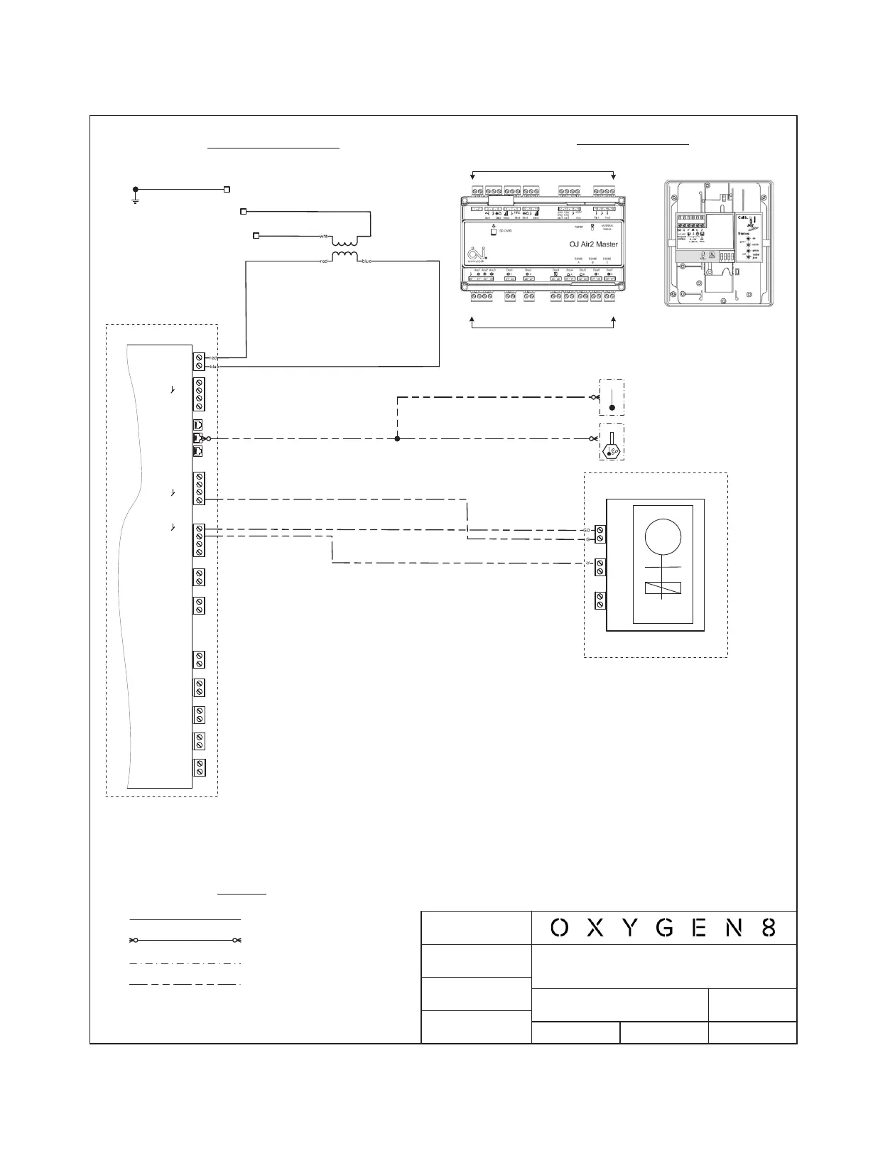
Controller Details
Wiring Diagram
T1
24VAC
N
T ER MI N ALS 20 TO 37
T ERMI N AL S 1 TO 19
b lk
OJ AIR2 MASTER
0
Legend
Factory wired
Communication/ RJ12
Enclosed unit
Fiel d wiri ng requ ired
T THT TH
GND
G ND
SUPP LY AIR TEMPERATURE
Refer to standard wiring
diagrams for panel wiring details.
COOL ING V AL VE
ACTUATOR
NOVA/ FIELD WIRING/HYDRONIC COOLING
WATER COIL
NOTE: Refer to standard wiring diagrams for default controls wiring.
VALVE ACTUATOR
M
G0
G
Y
M
U
Z
M
G0
G
Y
M
U
Z
1
OJ AIR2 MASTER
2
24VA C
16
17
18
19
T in 1
T in 2
A
B
C
RS485
RS485
RS485
20
21
22
23
Ao ut 1
Ao ut 2
Ao ut 3
24
25
D ou t1
26
27
D ou t2
28
29
D ou t3
30
31
D ou t4
32
33
D ou t5
34
35
D ou t6
36
37
D ou t4
12
13
14
15
Ain1
Ain2
+2 4V
POSITION SIGNAL 0-10 VDC/ 4 -2 0 mA
(Whe n optional R em ot e D uct Mo un t Tem pera tu re
S en so r TT H-6 202 and/o r Hum idity+Tem p Se ns or
is Provided)
HTHHTH
AIR HUMIDITY/TEMPERATURE
6.13 Field Wiring, Cooling Water Coil