3
B1d.1
4/06
Supercedes 8/05
PACOPACO
PACOPACO
PACO
PUMPS
I. INSTALLATION - MECHANICAL
All installations should be performed by personnel expe-
rienced with the placement, connection, and alignment
of pumping equipment. The following instructions are gen-
eral in nature, and may not deal with the specifics of
your installation. Read these instructions thoroughly
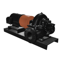
before installing and operating your PACO Type KP
Double Suction Centrifugal Split Case Pump. Suc-
cessful operation depends on careful attention to the pro-
cedures described in Sections I, II, III and IV of this
manual. Keep this instruction manual handy for future
use.
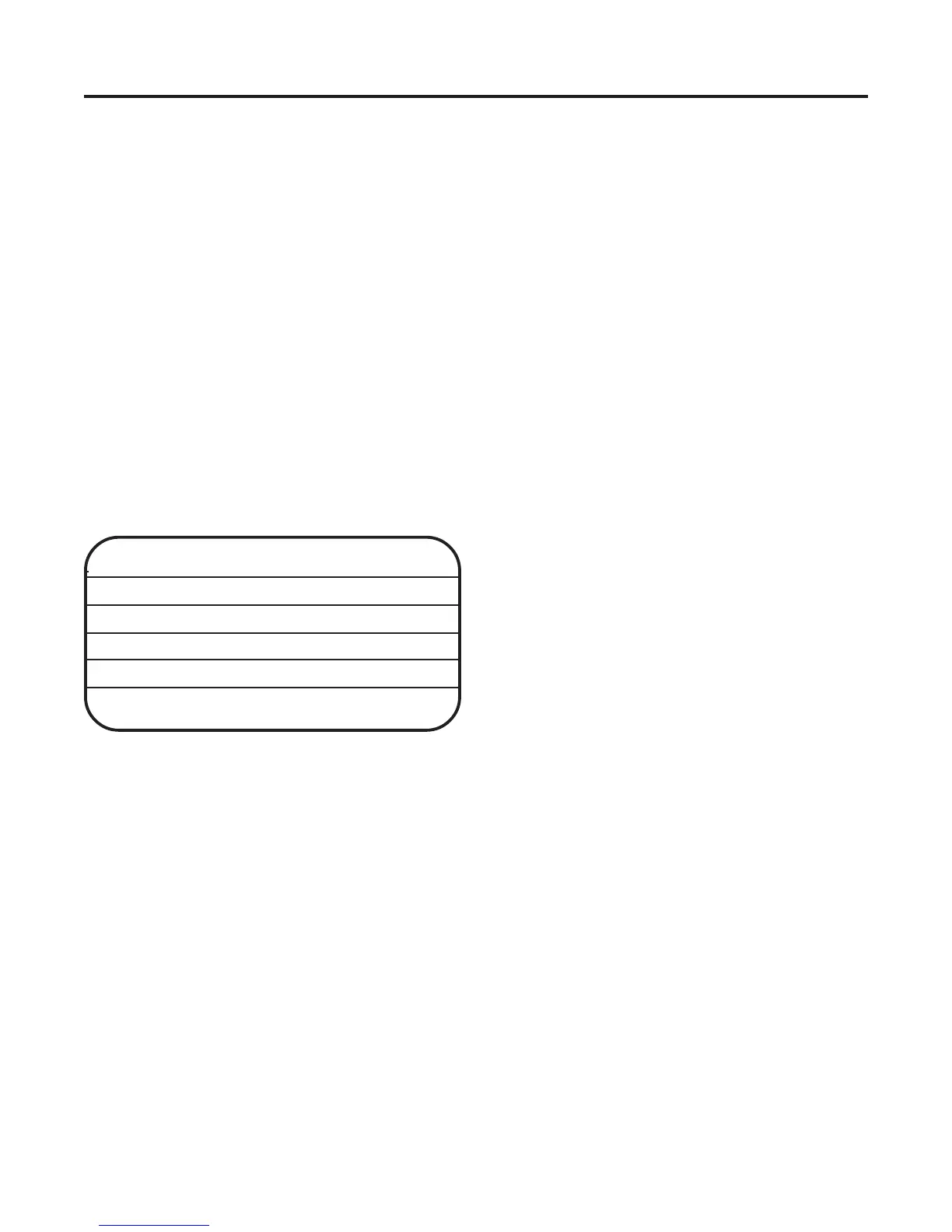
A. PUMP IDENTIFICATION
• All PACO Pumps are identified by Catalog and
Serial Numbers. These are stamped on the pump
nameplate (Figure 1) affixed to each pump casing
and should be referred to in all correspondence with
the Company.
PACOPACO
PACOPACO
PACO
FIGURE 1a
B. RECEIVING
• Check pumping unit for shortages and damages
immediately upon arrival. Pump accessories, when
required, are packaged in a separate container and
shipped with the unit.
• If equipment is damaged in transit, immediately
report the damage to the truck line’s agent.
Make a complete report on the freight bill to speed
satisfactory adjustment by the carrier.
• Unload and handle the equipment with a sling
or tow motor. Do not lift unit by lifting lugs on the
pump case or eye.
• Eyebolts on the motor! These are not intended to
support the complete pump assembly but to aid in
C. TEMPORARY STORAGE
• If the pump is not to be installed and operated within
a few days after arrival, store in a clean, dry area
of moderate ambient temperature.
• Rotate the shaft by hand monthly to coat the bear-
ings with lubricant and retard oxidation and corro-
sion.
• Where applicable, follow motor manufacturer’s
storage recommendations.
D. LOCATION
• Locate the pump as close to the suction supply as
possible. Use the shortest and most direct suc-
tion piping practical. Refer to paragraph H. SUC-
TION (INLET) PIPING.
• Locate the pump below system level wherever
possible. This will facilitate priming, assure a
steady liquid flow, and provide a positive suction
head.
• Make sure sufficient NPSH (Net Positive Suction
Head) is provided at the suction end by considering
the pump’s location in relation to the entire sys-
tem. Available NPSH must always equal or exceed
required NPSH specified on the pump performance
curve.
• Always allow sufficient accessibility for mainten-
ance and inspection. Provide a clear space with
ample head room for use of a hoist strong enough
to lift the unit.
• Make sure a suitable power source is available for
the pump motor. Electrical characteristics should
match those specified on the motor data plate,
within the limits covered in Sections II & III.
• Avoid pump exposure to sub-zero temperatures to
prevent pump liquid from freezing. If freezing
conditions exist during shutdown periods, seeSec-
tions IIIE and IIIF for specific recommendations.
E. PUMP FOUNDATION
• Your Type KP pump should be permanently installed
on a firm, concrete foundation mounting pad of suffi-
cient size to dampen any vibration and prevent any
deflection or misalignment. The pad may float on
springs or be a raised part of the equipment room
floor. The foundation should be poured without in-
terruption to 3/4 to 1-1/2 inches below the final pump
elevation. The top surface should be well scored or
CAT #: 29-20951-120061-1741
STOCK #:
SER #:
##
##
# 97X12345
GPM:280
IMP.
DIA.
“
BROOKSHIRE, TEXAS
34014412
Pumps
“”
“”“”
“”“”
“”’
TDH:264
8.4"
disassembly.